background image

11. Configuring the SPCN910 from a Browser 

Use FULL ENGINEER programming mode to configure and test the SPCN910 from the browser. 

¾


Select the 

Settings

Comms

. and then 

Modems

 menu options. The status of the primary and backup modems, if installed, is displayed.  

¾


Click on the 

Configure

 button for the IntelliModem Redcare modem. 

¾


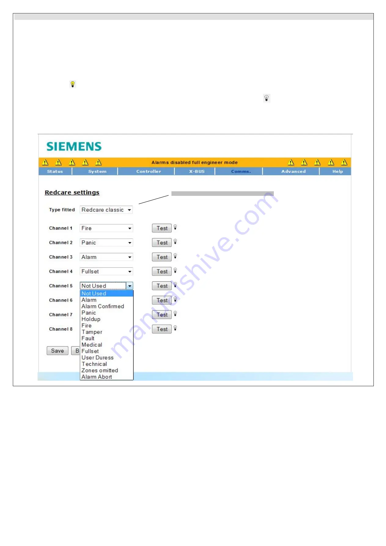
The

 Type fitted

 field which indicates the type of Redcare/DualCom ARD installed is not applicable for this Communication Interface Module  

¾


A list of eight channels is displayed. Select the alarm condition for each channel as required from the drop-down list.  

¾


Click on the 

Save

 button. 

To perform end-to-end testing of the SPCN910, the Redcare/DualCom ARD and transmission path for each of the channels: 

¾


Ensure that the Redcare/DualCom ARD is in test mode. (Check the Redcare/DualCom documentation) 

¾


Click the 

Test

 button located next to the required channel to test the alarm activation for that output. 


¾


The light bulb icon 

is switched on and the LED for that output is activated on the SPCN910. The corresponding LED on the Redcare/DualCom ARD 

blinks approximately three times to indicate that it is transmitting the test alarm to the ARC. 


¾


Wait approximately five seconds and click the 

Test

 button again for the same channel. T

he 

light bulb icon 

 is switched off and the output 

LED on the 

SPCN910 

switches off. The corresponding LED on the 

Redcare/DualCom ARD 

will blink again approximately three times 

to indicate it is transmitting a 

‘channel restore’ to the ARC

¾


Test the other channels using this procedure. 

¾


Contact the ARC service company to make sure that the alarms were correctly received. 


Note:

 Not applicable for this Communications Interface Module


Содержание SPCN910

Страница 1: ...SPCN910 Communication Interface Module en STEP A6V10324565 Edition 01 02 2011 1 1 2 3 4 5 6 7 8 9 10 11 12 13 14 15 16 3 5 8 7 6 1 4 2 ATS LF 1 2 1 2 3 4 5 4 1 4 2 3 3 6 8 4 7 GSM 1 2 4 3 5 5 1 3 2 4 ...

Страница 2: ...module to SPC controller Dimensions W x H x D 90 x 38 x 20 mm Weight 0 025 kg WARNING Before starting to install and work with this device please read the Safety Instructions WARNING Ensure that all anti static precautions are adhered to when handling connectors wires terminals and PCBs 2 Description of the SPCN910 The module connects to the SPC controller board via a 16 pin connector and is secur...

Страница 3: ...position P11 across 1 2 Wiring the ARD Wiring should be done with both the panel and ARD switched off Wire the V and 0V terminals on the ARD to the auxiliary power output on the SPC panel Connect channel outputs in the SPCN910 to the input terminals on the ARD as required Wire the C terminal on the ARD Fault relay to the 0V terminal on the ARD and the NC terminal on the ARD Fault Relay to the Line...

Страница 4: ...the Redcare DualCom ARD is in test mode Check the Redcare DualCom documentation Click the Test button located next to the required channel to test the alarm activation for that output The light bulb icon is switched on and the LED for that output is activated on the SPCN910 The corresponding LED on the Redcare DualCom ARD blinks approximately three times to indicate that it is transmitting the tes...

Страница 5: ... and backup modems if installed is displayed Enable the Redcare modem by ticking the Enabled check box if it is not currently enabled Select REDCARE in the Modem Type field if not already selected even if using DualCom The Redcare Modem Type field is not applicable for this Communication Interface Module A list of each of the eight channels is displayed Select the alarm condition for each channel ...

Отзывы: