Connection
6.3 Connecting the load cells
SIWAREX WP231
Manual, 07/2014, A5E31238908A-02
31
3.
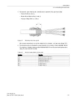
Twisted wire pairs that are also shielded are required for the specified cables:
–
Sensor cable (+) and (-)
–
Measuring voltage cable (+) and (-)
–
Supply voltage cable (+) and (-)
Figure 6-2
Shielding in the screw gland
We recommended that you use the cables listed in chapter →
Accessories (Page 175).
4.
The shield must be connected to ground directly in the vicinity of the SIWAREX WP231.
The maximum distance between the SIWAREX WP231 and the load cell applies when
using the recommended cables.
Table 6- 2
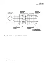
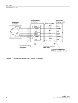
Load cell connections on the module
Labeling
Function
Sig-
Measurement cable load cell -
Sig+
Measurement cable load cell -
Sen-
Sensor cable load cell -
Sen+
Sensor cable load cell +
Exc-
Supply load cell -
Exc+
Supply load cell +
Содержание SIWAREX WP231
Страница 16: ...Safety notes 2 1 General safety instructions SIWAREX WP231 16 Manual 07 2014 A5E31238908A 02 ...
Страница 24: ...Application planning 4 2 Parameter assignment options SIWAREX WP231 24 Manual 07 2014 A5E31238908A 02 ...
Страница 108: ...Scale parameters and functions 8 15 DR 15 tare settings SIWAREX WP231 108 Manual 07 2014 A5E31238908A 02 ...
Страница 131: ...Scale parameters and functions 8 26 DR 48 date and time 2 for Modbus SIWAREX WP231 Manual 07 2014 A5E31238908A 02 131 ...
Страница 132: ......
Страница 174: ...Technical data 13 3 Approvals SIWAREX WP231 174 Manual 07 2014 A5E31238908A 02 ...
Страница 180: ...List of abbreviations SIWAREX WP231 180 Manual 07 2014 A5E31238908A 02 ...
Страница 182: ...Index SIWAREX WP231 182 Manual 07 2014 A5E31238908A 02 ...

