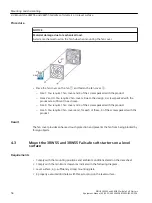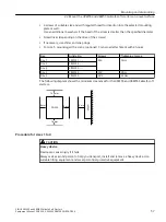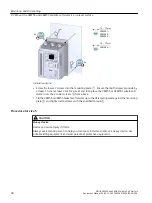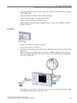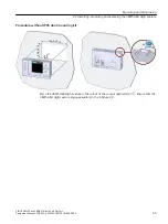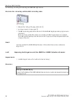
Procedure for connecting with the HMI connecting cable
• Observe the coding of the plug and socket
①
.
• Lock the connector in the socket
②
.
• The HMI connecting cable in the cable duct of the 3RW5 HMI High Feature may only be routed
downward.
Make sure that you install the cable in accordance with EMC requirements. For example,
route data cables separately from the motor cable. Connect both sides of shielded cables over
a large surface area.
Result
You have installed the 3RW5 HMI High Feature in the cabinet door and can commission
(Page 127) it.
4.4.5
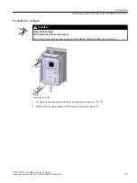
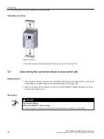
Replacing the hinged cover of the 3RW55 or 3RW55 Failsafe soft starter
Requirements
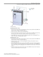
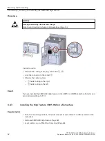
• Suitable hinged cover with or without cutout (accessory)
Procedure
NOTICE
Damage to the HMI display
Ensure that the display of the 3RW5 HMI High Feature does not sustain damage when replacing
the hinged cover.
Mounting and dismantling
4.4 Installing, mounting and removing the 3RW5 HMI High Feature
SIRIUS 3RW55 and 3RW55 Failsafe Soft Starters
68
Equipment Manual, 02/2022, A5E35630887002A/RS-AF/006


