Connection
8.4 Connection cross-sections
SIRIUS Innovations - SIRIUS 3RU2 thermal overload relays / SIRIUS 3RB3 solid-state overload relays
72
Manual, 09/2014, A5E03656507420A/RS-AA/002
8.4.3
Conductor cross-sections for ring cable lug connection system
Conductor cross-sections for ring cable lug connection system
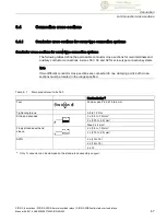
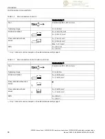
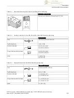
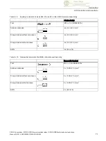
The tables below define the permissible conductor cross-sections for main terminals and
auxiliary conductor connections in sizes S00 and S0 for ring cable lug connection systems.
Table 8- 11 Main conductors and auxiliary conductors of size S00 with M3 combination screws
SIRIUS devices
Tool
Pozidriv size 2,
Ø 5 to 6 mm
Tightening torque
0.8 to 1.2 Nm
Ring cable lug
1)
d
2
= min. 3.2 mm
d
3
= max. 7.5 mm
Table 8- 12 Main conductors and auxiliary conductors of size S0 with M4 combination screws
SIRIUS devices
Tool
Pozidriv size 2,
Ø 5 to 6 mm
Tightening torque
2.0 to 2.5 Nm
Ring cable lug
1)
d
2
= min. 4.3 mm
d
3
= max. 12.2 mm
1)
The following ring cable lugs are approved for achieving the required clearances and
creepage distances:
●
For applications according to IEC 60947-1:
–
DIN 46237 (with insulating sleeve)
–
JIS CS805 type RAV (with insulating sleeve)
–
JIS CS805 type RAP (with insulating sleeve)
●
For applications according to UL 508:
–
DIN 46 234 (without insulating sleeve)
–
DIN 46225 (without insulating sleeve)
–
JIS CS805 (without insulating sleeve)

