Functions
2.15 Sensitive Earth Flt.(comp/ isol. starp.)
SIPROTEC, 7SD5, Manual
C53000-G1176-C169-5, Release date 02.2011
298
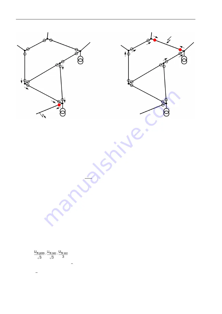
Figure 2-151
Faulted line location in meshed networks using directional indications
2.15.2
Setting Notes
General
This section applies only to relay models with earth fault detection module and only when these are used in
networks with isolated or compensated starpoint. In other cases, this section can be skipped.
Earth fault detection is only possible if the function
Sens. Earth Flt
(address
130
) was set to
Enabled
during configuration. If the device is equipped with earth fault detection but is to operate in an earthed network,
address
130
Sens. Earth Flt
must be set to
Disabled
!
The earth fault detection can be switched
ON: with Trip
,
OFF
or set to
Alarm Only
at address
3001
Sens.
Earth Flt
. In the latter case (default setting) the device announces detected earth faults, identifies the faulty
phase and the earth fault direction according to the other settings.
If the earth fault detection is switched
ON: with Trip
it also issues a trip command. In this case no earth
fault protocol is generated, but a trip log that registers all information about the earth fault and the earth fault
tripping. The tripping can be delayed via address
3007
T 3U0>
.
Voltage Stages
The displacement voltage is the pickup threshold of the earth fault detection and is set in address
3002
3U0>
.
If the displacement voltage U
en
of the voltage transformer set is directly connected to the fourth voltage mea-
suring input U
4
of the device and if this was predefined during the configuration, the device will use this voltage,
multiplied by the factor
Uph / Udelta
(address
211
). For the usual transformation of the voltage transformer
with e–n–winding
the factor is set to 1.73 (
√
3) (see also Subsection 2.1.2.1, margin heading „Voltage Transformer Connection“).
In case of a complete displacement of a healthy voltage triangle the displacement voltage has a value that is
√
3 times the phase-to-phase voltage.
Содержание SIPROTEC
Страница 20: ...Contents SIPROTEC 7SD5 Manual C53000 G1176 C169 5 Release date 02 2011 20 ...
Страница 351: ...Functions 2 18 Synchronism and Voltage Check optional SIPROTEC 7SD5 Manual C53000 G1176 C169 5 Release date 02 2011 351 ...
Страница 494: ...Functions 2 27 Command Processing SIPROTEC 7SD5 Manual C53000 G1176 C169 5 Release date 02 2011 494 ...
Страница 640: ...Technical Data 4 27 Dimensions SIPROTEC 7SD5 Manual C53000 G1176 C169 5 Release date 02 2011 640 ...
Страница 657: ...Appendix A 2 Terminal Assignments SIPROTEC 7SD5 Manual C53000 G1176 C169 5 Release date 02 2011 657 7SD5 W ...
Страница 754: ...Appendix A 10 Measured Values SIPROTEC 7SD5 Manual C53000 G1176 C169 5 Release date 02 2011 754 ...
Страница 756: ...Literature SIPROTEC 7SD5 Manual C53000 G1176 C169 5 Release date 02 2011 756 ...
Страница 768: ...Glossary SIPROTEC 7SD5 Manual C53000 G1176 C169 5 Release date 02 2011 768 ...


