


2.21 Disconnection of Measuring Locations
297
7UT613/63x Manual
C53000-G1176-C160-2
2.21
Disconnection of Measuring Locations
2.21.1 Functional Description
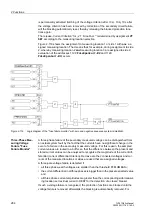
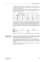
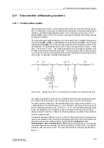
During maintenance work, or when parts of the system are shut down during opera-
tion, it is sometimes necessary to suspend the processing of individual measuring lo-
cations by the differential protection system. For maintenance work on the circuit
breaker
CBC
in Figure 2-123, for instance, the breaker would be isolated by opening
the adjacent isolators.
The main protected object transformer is in this example fed on side
S1
through mea-
suring locations
M1
and
M2
, on side
S2
lies the measuring location
M3
. Assuming the
measuring location
M2
should now be suspended due to the maintenance work on the
circuit breaker. If this information is sent to the device through a binary input — in this
case
„>disconnect M2“
–, the measuring location will no longer be included in the
formation of the differential protection values. The measuring location is disconnected,
i.e. any kind of work can be performed there without affecting any operating function
of the sides, for example, the differential protection.
Figure 2-123
Arrangement with 1
1
/
2
circuit breakers (3 breakers for 2 transformer feeders)
Any measuring location can be disconnected by means of an appropriate binary input.
In 1-phase busbar protection, such a binary input can be used for each feeder.
The disconnection works only in the specified frequency range of the protection, i.e. f
N
= 50/60 Hz from 10 to 66 Hz and for f
N
= 16.7 Hz from 10 to 22 Hz. If the current cri-
terion is disabled via binary input
„>disconn. I>=0“
, the specified frequency range
is also not applicable. The activation is thus not suited for blocking the protection
during startup of a machine. Instead, the blocking features provided in the protection
functions must be used.
The isolation becomes effective only if no current is flowing through the measuring lo-
cation to be isolated. This is ensured by checking whether the current arriving from the
measuring location has dropped below the threshold
PoleOpenCurr.M1
,
PoleOpenCurr.M2
to
PoleOpenCurr.M5
of the measuring location. Once the dis-
connection has become effective, this fact is reported by a binary input, e.g. with the
indication
„M2 disconnected“
. The current threshold is no longer checked from
then on.
Содержание SIPROTEC 7UT613 series
Страница 16: ...Contents 16 7UT613 63x Manual C53000 G1176 C160 2 Literature 631 Glossary 623 Index 633 ...
Страница 30: ...1 Introduction 30 7UT613 63x Manual C53000 G1176 C160 2 ...
Страница 506: ...A Appendix 506 7UT613 63x Manual C53000 G1176 C160 2 7UT633 D E ...
Страница 508: ...A Appendix 508 7UT613 63x Manual C53000 G1176 C160 2 7UT633 P Q ...
Страница 510: ...A Appendix 510 7UT613 63x Manual C53000 G1176 C160 2 7UT635 D E ...
Страница 512: ...A Appendix 512 7UT613 63x Manual C53000 G1176 C160 2 7UT635 P Q ...
Страница 515: ...A 2 Terminal Assignments 515 7UT613 63x Manual C53000 G1176 C160 2 7UT633 B ...
Страница 516: ...A Appendix 516 7UT613 63x Manual C53000 G1176 C160 2 7UT633 B Figure A 7 General diagram 7UT633 panel surface mounting ...
Страница 517: ...A 2 Terminal Assignments 517 7UT613 63x Manual C53000 G1176 C160 2 7UT633 N ...
Страница 518: ...A Appendix 518 7UT613 63x Manual C53000 G1176 C160 2 7UT633 N Figure A 8 General diagram 7UT633 panel surface mounting ...
Страница 519: ...A 2 Terminal Assignments 519 7UT613 63x Manual C53000 G1176 C160 2 7UT635 B ...
Страница 520: ...A Appendix 520 7UT613 63x Manual C53000 G1176 C160 2 7UT635 B Figure A 9 General diagram 7UT635 panel surface mounting ...
Страница 521: ...A 2 Terminal Assignments 521 7UT613 63x Manual C53000 G1176 C160 2 7UT635 N ...
Страница 522: ...A Appendix 522 7UT613 63x Manual C53000 G1176 C160 2 7UT635 N Figure A 10 General diagram 7UT635 panel surface mounting ...
Страница 622: ...A Appendix 622 7UT613 63x Manual C53000 G1176 C160 2 ...
Страница 632: ...Literature 632 7UT613 63x Manual C53000 G1176 C160 2 ...


