


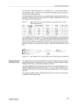


2 Functions
288
7UT613/63x Manual
C53000-G1176-C160-2
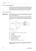
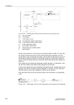
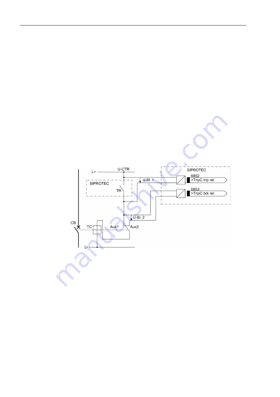
2.19.2 Trip Circuit Supervision
The differential protection relay 7UT613/63x is equipped with an integrated trip circuit
supervision. Depending on the number of binary inputs with isolated control inputs that
are still available, a choice can be made between monitoring with one or two binary
inputs. If the masking of the required binary inputs does not match the selected mon-
itoring type, then a message to this effect is generated (
„TripC ProgFail“
).
2.19.2.1 Function Description
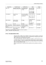
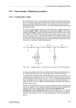
Supervision Using
Two Binary Inputs
If two binary inputs are used, they are connected according to figure 2-117, one in par-
allel to the assigned command relay contact of the protection and the other parallel to
the circuit breaker auxiliary contact.
A precondition for the use of the trip circuit supervision is that the control voltage for
the circuit breaker is higher than the total of the minimum voltages drops at the two
binary inputs (U
Ctrl
> 2·U
BImin
). Since at least 19 V are needed for each binary input,
the supervision function can only be used with a system control voltage of more than
38 V.
Figure 2-117
Principle of trip circuit supervision using two binary inputs
TR
Trip relay contact
CB
Circuit breaker
TC
Circuit breaker trip coil
Aux1
Circuit breaker auxiliary contact (make)
Aux2
Circuit breaker auxiliary contact (break)
U
Ft
Control voltage (trip voltage)
U
BI1
Input voltage of 1st binary input
U
BI2
Input voltage of 2nd binary input
The diagram shows the circuit breaker in closed state.
Depending on the state of the trip relay and the circuit breaker s auxiliary contacts, the
binary inputs are triggered (logical state „H“ in the following table) or short-circuited
(logical state and „L“).
Содержание SIPROTEC 7UT613 series
Страница 16: ...Contents 16 7UT613 63x Manual C53000 G1176 C160 2 Literature 631 Glossary 623 Index 633 ...
Страница 30: ...1 Introduction 30 7UT613 63x Manual C53000 G1176 C160 2 ...
Страница 506: ...A Appendix 506 7UT613 63x Manual C53000 G1176 C160 2 7UT633 D E ...
Страница 508: ...A Appendix 508 7UT613 63x Manual C53000 G1176 C160 2 7UT633 P Q ...
Страница 510: ...A Appendix 510 7UT613 63x Manual C53000 G1176 C160 2 7UT635 D E ...
Страница 512: ...A Appendix 512 7UT613 63x Manual C53000 G1176 C160 2 7UT635 P Q ...
Страница 515: ...A 2 Terminal Assignments 515 7UT613 63x Manual C53000 G1176 C160 2 7UT633 B ...
Страница 516: ...A Appendix 516 7UT613 63x Manual C53000 G1176 C160 2 7UT633 B Figure A 7 General diagram 7UT633 panel surface mounting ...
Страница 517: ...A 2 Terminal Assignments 517 7UT613 63x Manual C53000 G1176 C160 2 7UT633 N ...
Страница 518: ...A Appendix 518 7UT613 63x Manual C53000 G1176 C160 2 7UT633 N Figure A 8 General diagram 7UT633 panel surface mounting ...
Страница 519: ...A 2 Terminal Assignments 519 7UT613 63x Manual C53000 G1176 C160 2 7UT635 B ...
Страница 520: ...A Appendix 520 7UT613 63x Manual C53000 G1176 C160 2 7UT635 B Figure A 9 General diagram 7UT635 panel surface mounting ...
Страница 521: ...A 2 Terminal Assignments 521 7UT613 63x Manual C53000 G1176 C160 2 7UT635 N ...
Страница 522: ...A Appendix 522 7UT613 63x Manual C53000 G1176 C160 2 7UT635 N Figure A 10 General diagram 7UT635 panel surface mounting ...
Страница 622: ...A Appendix 622 7UT613 63x Manual C53000 G1176 C160 2 ...
Страница 632: ...Literature 632 7UT613 63x Manual C53000 G1176 C160 2 ...


