


2.7 Single-Phase Time Overcurrent Protection
199
7UT613/63x Manual
C53000-G1176-C160-2
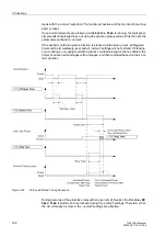
Figure 2-87
Earth fault protection using the high-impedance principle
In case of an earth fault in the protection zone (figure2-87 right) a starpoint current
I
St
will certainly be present. The earthing conditions in the rest of the network determine
how strong a zero sequence current from the system is. A secondary current which is
equal to the total fault current tries to pass through the resistor R. Since the latter is
high-ohmic, a high voltage emerges immediately. Therefore, the current transformers
get saturated. The RMS voltage across the resistor approximately corresponds to the
knee-point voltage of the current transformers.
Resistance R is dimensioned such that, even with the very lowest earth fault current
to be detected, it generates a secondary voltage, which is equal to half the saturation
voltage of current transformers (see also notes on "Dimensioning" in subsection
2.7.4).
High-Impedance
Protection with
7UT613/63x
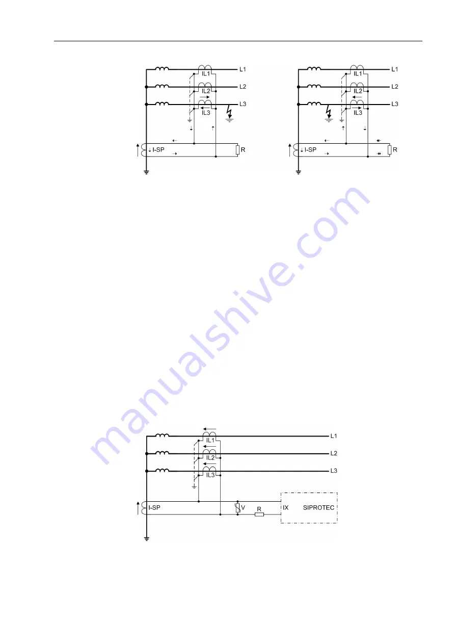
With 7UT613/63x a high-sensitivity single-phase measuring input is used for high-im-
pedance protection. As this is a current input, the protection detects current through
the resistor instead of the voltage across resistor R.
Figure 2-88 shows the connection example. The 7UT613/63x is connected in series
to resistor R and measures its current.
Varistor V limits the voltage when internal faults occur. High voltage peaks emerging
with transformer saturation are cut by the varistor. At the same time, voltage is
smoothed without reduction of the mean value.
Figure 2-88
Connection scheme for restricted earth fault protection according to the high-im-
pedance principle
Содержание SIPROTEC 7UT613 series
Страница 16: ...Contents 16 7UT613 63x Manual C53000 G1176 C160 2 Literature 631 Glossary 623 Index 633 ...
Страница 30: ...1 Introduction 30 7UT613 63x Manual C53000 G1176 C160 2 ...
Страница 506: ...A Appendix 506 7UT613 63x Manual C53000 G1176 C160 2 7UT633 D E ...
Страница 508: ...A Appendix 508 7UT613 63x Manual C53000 G1176 C160 2 7UT633 P Q ...
Страница 510: ...A Appendix 510 7UT613 63x Manual C53000 G1176 C160 2 7UT635 D E ...
Страница 512: ...A Appendix 512 7UT613 63x Manual C53000 G1176 C160 2 7UT635 P Q ...
Страница 515: ...A 2 Terminal Assignments 515 7UT613 63x Manual C53000 G1176 C160 2 7UT633 B ...
Страница 516: ...A Appendix 516 7UT613 63x Manual C53000 G1176 C160 2 7UT633 B Figure A 7 General diagram 7UT633 panel surface mounting ...
Страница 517: ...A 2 Terminal Assignments 517 7UT613 63x Manual C53000 G1176 C160 2 7UT633 N ...
Страница 518: ...A Appendix 518 7UT613 63x Manual C53000 G1176 C160 2 7UT633 N Figure A 8 General diagram 7UT633 panel surface mounting ...
Страница 519: ...A 2 Terminal Assignments 519 7UT613 63x Manual C53000 G1176 C160 2 7UT635 B ...
Страница 520: ...A Appendix 520 7UT613 63x Manual C53000 G1176 C160 2 7UT635 B Figure A 9 General diagram 7UT635 panel surface mounting ...
Страница 521: ...A 2 Terminal Assignments 521 7UT613 63x Manual C53000 G1176 C160 2 7UT635 N ...
Страница 522: ...A Appendix 522 7UT613 63x Manual C53000 G1176 C160 2 7UT635 N Figure A 10 General diagram 7UT635 panel surface mounting ...
Страница 622: ...A Appendix 622 7UT613 63x Manual C53000 G1176 C160 2 ...
Страница 632: ...Literature 632 7UT613 63x Manual C53000 G1176 C160 2 ...


