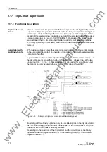

2.17 Trip Circuit Supervision
171
7ST6 Manual
E50417-G1176-C251-A3
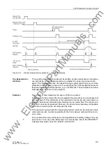
A state in which both binary inputs are not activated („L“) is only possible in healthy trip
circuits for a short transition period (trip relay contact closed but circuit breaker not yet
open).
A continuous state of this condition is only possible when the trip circuit has been in-
terrupted, a short-circuit exists in the trip circuit, a loss of battery voltage occurs, or
malfunctions occur with the circuit breaker mechanism. Therefore, it is used as moni-
toring criterion.
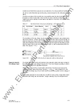
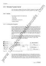
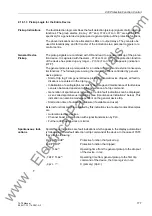
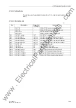
Table 2-7
Condition table for binary inputs, depending on RTC and CB position
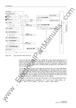
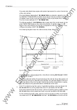
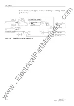
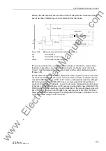
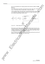
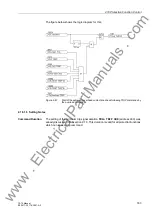
The conditions of the two binary inputs are checked periodically. A query takes place
about every 500 ms. If three consecutive conditional checks detect an abnormality, an
alarm is output (see Figure 2-50). The repeated measurements determine the delay
of the fault indication and avoid that an alarm is output during short transition periods.
After the fault in the trip circuit is removed, the alarm is reset automatically after the
same time (approx. 1.5 s).
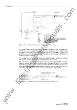
Figure 2-50
Logic diagram of the trip circuit supervision with two binary inputs
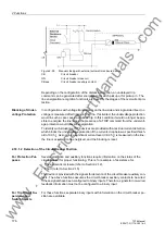
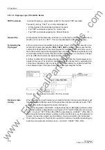
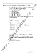
Supervision with
One Binary Input
The binary input is connected in parallel to the respective command relay contact of
the protection device according to Figure 2-51. The circuit breaker auxiliary contact is
bridged with a high-ohm substitute resistor R.
The control voltage for the circuit breaker should be at least twice as high as the
minimum voltage drop at the binary input (U
Ctrl
> 2 U
BImin
). Since at least 19 V are
needed for the binary input, the monitor can be used with a system control voltage of
over 38 V.
A calculation example for the resistance shunt R is shown in the configuration notes
in Section „Mounting and Connections“, margin heading „Trip Circuit Supervision“.
No
.
Trip Contact
Circuit Breaker
Aux 1
Aux 2
BI 1 BI 2
1
Open
CLOSE
Closed
Open
H
L
2
Open
OPEN Open
Closed
H
H
3
Closed
CLOSE
Closed
Open
L
L
4
Closed
OPEN Open
Closed
L
H
www
. ElectricalPartManuals
. com
Содержание SIPROTEC 7ST6
Страница 14: ...Contents 14 7ST6 Manual E50417 G1176 C251 A3 w w w E l e c t r i c a l P a r t M a n u a l s c o m ...
Страница 24: ...1 Introduction 24 7ST6 Manual E50417 G1176 C251 A3 w w w E l e c t r i c a l P a r t M a n u a l s c o m ...
Страница 254: ...3 Mounting and Commissioning 254 7ST6 Manual E50417 G1176 C251 A3 w w w E l e c t r i c a l P a r t M a n u a l s c o m ...
Страница 288: ...4 Technical Data 288 7ST6 Manual E50417 G1176 C251 A3 w w w E l e c t r i c a l P a r t M a n u a l s c o m ...
Страница 340: ...A Appendix 340 7ST6 Manual E50417 G1176 C251 A3 w w w E l e c t r i c a l P a r t M a n u a l s c o m ...
Страница 342: ...Literature 342 7ST6 Manual E50417 G1176 C251 A3 w w w E l e c t r i c a l P a r t M a n u a l s c o m ...
Страница 354: ...Index 354 7ST6 Manual E50417 G1176 C251 A3 w w w E l e c t r i c a l P a r t M a n u a l s c o m ...
Страница 355: ...Index 355 7ST6 Manual E50417 G1176 C251 A3 w w w E l e c t r i c a l P a r t M a n u a l s c o m ...
Страница 356: ...Index 356 7ST6 Manual E50417 G1176 C251 A3 w w w E l e c t r i c a l P a r t M a n u a l s c o m ...