


Functions
2.8 Motor Protection
SIPROTEC, 7SJ62/64, Manual
C53000-G1140-C207-2, Release date 01.2008
160
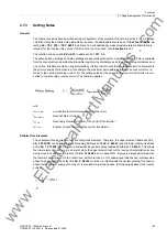
The tripping time is calculated based on the following equation:
with
t
TRIP
Actual tripping time for flowing current
I
t
max STARTUP
Tripping time for nominal startup current
I
STARTUP
(address
4103
,
STARTUP TIME
or
4105
,
STARTUP T WARM
)
I
Current actually flowing (measurement value)
I
STARTUP
Nominal startup current of the motor (address
4102
,
STARTUP CURRENT
)
I
MOTOR START
Pickup value for recognition of motor startup (address
1107
,
I MOTOR START
),
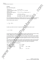
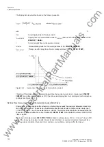
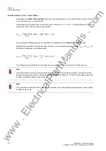
Figure 2-52
Inverse time tripping curve for motor starting current
Therefore, if the startup current
I
is smaller (larger) than the nominal current
I
STARTUP
(parameter
STARTUP
CURRENT
) as configured under address
4102
, then the actual tripping time t
Trip
is prolonged (or shortened) ac-
cordingly (see Figure 2-52).
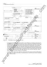
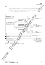
Definite Time Overcurrent Tripping Characteristic (Locked Rotor Time)
Tripping must be executed when the actual motor starting time exceeds the maximum allowable locked rotor
time if the rotor is locked. The device can be informed about the locked rotor condition via the binary input
(
„>Rotor locked“
), e.g. from an external r.p.m. monitor. The motor startup condition is assumed when the
current in any phase exceeds the current threshold
I MOTOR START
. At this instant, the timer LOCK ROTOR
TIME is started.
The locked rotor delay time (
LOCK ROTOR TIME
) is linked to a binary input
„>Rotor locked“
via an AND
gate. If the binary input is picked up after the set locked rotor time has expired, immediate tripping will take
place regardless of whether the locked rotor condition occurred before, during or after the timeout.
www
. ElectricalPartManuals
. com


