Appendix
A-6
7SA522 Manual
C53000-G1176-C119-2
1.2
General Diagrams
1.2.1
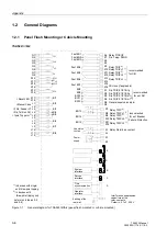
Panel Flush Mounting or Cubicle Mounting
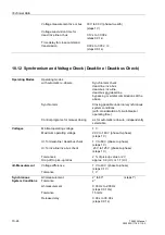
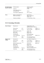
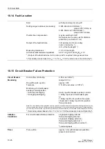
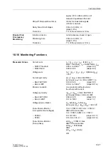
7SA522
∗
−
∗
A/J
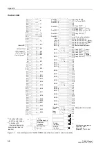
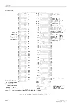
Figure 1-1
General diagram for 7SA522
∗
–
∗
A/J (panel flush mounted or cubicle mounted)
Power
Earthing at the
supply
rear wall
Q1
Q2
I
L1
Q7
Q8
I
4
Q3
Q4
I
L2
Q5
Q6
I
L3
R13
R14
U
4
R15
R17
U
L1
R16
K17
K18
BI1
U
L2
J3
J4
BI3
J5
J6
BI4
BI5
K1
K2
( )
~
+
-
R1
R2
BO8
R3
BO9
R5
BO10
K9
K10
Fast BO4
K11
K12
Fast BO5
R18
U
L3
J1
J2
BI2
J7
J8
BI6
J9
J10
BI7
J11
J12
BI8
K6
K7
K8
Fast BO2
K5
Fast BO3
Fast BO1
K13
K14
Fast BO6
K15
K16
Fast BO7
R4
R6
BO12
BO11
R7
R8
BO13
R9
R10
BO14
R11
R12
BO15
B
C
A
Operator
interface
D
E
Live status
K3
K4
contact
1 2
3 2
Interference suppression
capacitors at the
Ceramic, 4.7 nF, 250 V
Time
synchronization
Service
interface
System
interface
relay contacts,
>Reset LED
>Manual Close
>FAIL: Feeder VT
>Dis.Tel.Rec.Ch1
>1poleTrip perm.
1)
1)
in devices with single-
2)
in devices with
(refer also to tables 5-5
and three-pole tripping
three-pole tripping only
and 5-6)
Relay PICKUP
Dis. Telep. SEND
Relay TRIP
2)
Relay TRIP L1
1)
Relay TRIP L2
1)
Relay TRIP
2)
Relay TRIP L3
1)
recommended
for CB
Dis. TRIP Z1/Z1B, 1p
Dis. TRIP Z1/Z1B, 3p
Dis. TRIP Z1/Z1B, sf
2)
Dis. TRIP Z1/Z1B, mf
2)
General supervision alarm
Relay TRIP
2)
Relay TRIP L1
1)
Relay TRIP L2
1)
Relay TRIP
2)
Relay TRIP L3
1)
recommended
for ext. Breaker
Failure Protection
recommended
for ext. AR
Relay Alarm/Live contact
1 2
3 2
AR close (if applicable)
Содержание siprotec 7SA522
Страница 20: ...7SA522 Manual C53000 G1176 C119 2 ...
Страница 64: ...7SA522 Manual C53000 G1176 C119 2 ...
Страница 89: ...SIPROTEC 4 Devices 4 25 7SA522 Manual C53000 G1176 C119 2 Figure 4 20 CFC Logic example ...
Страница 408: ...7SA522 Manual C53000 G1176 C119 2 ...
Страница 456: ...7SA522 Manual C53000 G1176 C119 2 ...
Страница 516: ...7SA522 Manual C53000 G1176 C119 2 ...
Страница 620: ...Appendix B 48 ...

