Functions
6-242
7SA522 Manual
C53000-G1176-C119-2
Trip Dependent
Messages
The latching of fault messages, allocated to the device LEDs and the storage of spon-
taneous messages may be made dependant on whether the device has issued a trip
command. This information is then not output if during a system disturbance one or
more protection functions have picked up, but no tripping by the 7SA522 resulted be-
cause the fault was cleared by a different device (e.g. on another line). In this manner,
these messages are restricted to faults occuring on the protected feeder.
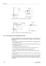
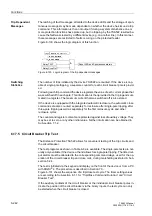
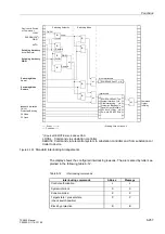
Figure 6-130 shows the logic diagram of this function.
Figure 6-130 Logic diagram of the trip dependent messages
Switching
Statistics
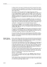
The number of trips initiated by the device 7SA522 are counted. If the device is cap-
able of single-pole tripping, a separate counter for each circuit breaker pole is provid-
ed.
Following each trip command the device registers the value of each current phase that
was switched off in each pole. This information is then provided in the trip log and sum-
mated in a register. The maximum current that was switched off is also stored.
If the device is equipped with the integrated automatic reclosure, the automatic close
commands are also counted, separately for reclosure after single-pole tripping, after
three-pole tripping as well as separately for the first reclosure cycle and other
reclosure cycles.
The counter and register contents are protected against loss of auxiliary voltage. They
may be set to zero or any other initial value. Further information can be obtained in
Sub-section 7.1.2.
6.17.5 Circuit Breaker Trip Test
The Distance Protection 7SA522 allows for convenient testing of the trip circuits and
the circuit breaker.
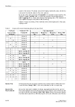
The test programs as shown in Table 6-8 are available. The single-pole tests are nat-
urally only available if the device at hand allows for single-pole tripping. The listed out-
put alarms must be allocated to the corresponding command relays, used for the op-
eration of the circuit breaker trip and close coils, during marshalling as stated in Sub-
section 5.2.4.
The test is initiated via the keypad and display on the front of the device or from a PC
with DIGSI
®
4. The procedure is described in Section 7.3..
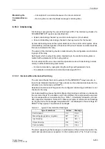
Figure 6-131 shows the sequence of a trip/close test cycle. The timer setting values
are according to Sub-section 6.1.1 for “Trip/Close Command Duration” and “Circuit
Breaker Test”.
If the auxiliary contacts of the circuit breaker or the individual circuit breaker poles in-
dicate the position of the circuit breaker via the binary inputs, the test cycle can only
be started when the circuit breaker is closed.
&
ZLWK3,&.83
ZLWK75,3
)OW'LVS/('/&'
Relay TRIP
„1“
Relay Drop Out
Reset LED and Spontaneous alarms
Содержание siprotec 7SA522
Страница 20: ...7SA522 Manual C53000 G1176 C119 2 ...
Страница 64: ...7SA522 Manual C53000 G1176 C119 2 ...
Страница 89: ...SIPROTEC 4 Devices 4 25 7SA522 Manual C53000 G1176 C119 2 Figure 4 20 CFC Logic example ...
Страница 408: ...7SA522 Manual C53000 G1176 C119 2 ...
Страница 456: ...7SA522 Manual C53000 G1176 C119 2 ...
Страница 516: ...7SA522 Manual C53000 G1176 C119 2 ...
Страница 620: ...Appendix B 48 ...

