Functions
6-60
7SA522 Manual
C53000-G1176-C119-2
.
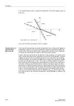
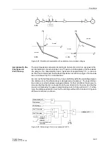
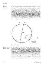
Figure 6-33 Phasor diagram of the MHO circle measured values
For each distance zone a MHO circle can be defined by means of the parameter Z
r
. It
is also possible to select for each zone whether its reach should be in the
)RUZDUG
or
5HYHUVH
direction.For the reverse direction, the MHO circle is mirrored in the origin
of the coordinate system. As soon as the fault impedance of any loop is confidently
measured inside the MHO circle of a distance zone, the affected loop is designated as
picked up. The loop information is also converted to phase segregated information.
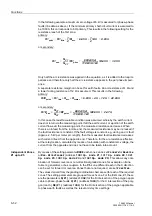
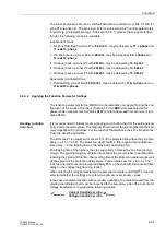
Further conditions for the pick-up of a zone is that the zone may not be blocked by the
power swing blocking (refer also to Sub-section 6.3.1). Furthermore the distance pro-
tection may not be blocked or switched off completely. Figure 6-34 shows these con-
ditions.
Figure 6-34 Release logic of a zone (Z1 used as an example)
L
oad
ar
ea
Z
r
R
Load
k · Z
v
Z
r
= Impedance reach limit (set value)
Z
F
= Fault impedance
Z
S
= Source impedance
k = Weighting factor for
polarizing voltage
∆
Z
1
∆
Z
2
Z
F
R
jX
Dis switched off
Dis blocked
≥
1
Pow.swing block
UHYHUVH
IRUZDUG
LQDFWLYH
≥
1
&
2SPRGH=
„1“
&
further
zones
*)
IRUZDUG
and
UHYHUVH
only af-
fect the measured values, but
have no effect on this logic
release of Z1
Содержание siprotec 7SA522
Страница 20: ...7SA522 Manual C53000 G1176 C119 2 ...
Страница 64: ...7SA522 Manual C53000 G1176 C119 2 ...
Страница 89: ...SIPROTEC 4 Devices 4 25 7SA522 Manual C53000 G1176 C119 2 Figure 4 20 CFC Logic example ...
Страница 408: ...7SA522 Manual C53000 G1176 C119 2 ...
Страница 456: ...7SA522 Manual C53000 G1176 C119 2 ...
Страница 516: ...7SA522 Manual C53000 G1176 C119 2 ...
Страница 620: ...Appendix B 48 ...


