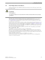
Phase Rotation
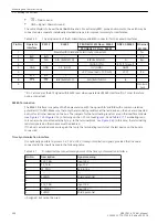
The phase rotation must correspond to the configured phase rotation, in general a clockwise phase rotation. If
the system has an anti-clockwise phase rotation, this must have been considered when the power system data
was set (address 235
PHASE SEQ.
). Incorrect direction of rotation is indicated
Fail Ph. Seq.
(No. 171.
The measured value phase allocation must be checked and corrected, if required, after the line has been
isolated and current transformers have been short-circuited. The phase rotation check must then be repeated.
VT miniature circuit breaker
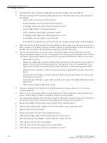
Open the miniature circuit breaker of the feeder voltage transformers. The measured voltages in the opera-
tional measured values appear with a value close to zero (small measured voltages are of no consequence).
Check in the spontaneous indications that the VT mcb trip was entered (Indication
>FAIL:Feeder VT
“ON”
in the spontaneous indications). Beforehand it has to be assured that the position of the VT mcb is connected
to the device via a binary input.
Close the VT mcb again: The above indication appears in the spontaneous indications as “OFF”, i.e.,
>FAIL:Feeder VT
“OFF”
If one of the annunciations does not appear, check the connection and allocation of these signals.
If the “ON” state and the “OFF” state are swapped, the contact type (H-active or L-active) must be checked and
corrected.
If synchronism check is used and if the assigned VT mcb auxiliary contact is connected to the device, its func-
tion must also be checked. When switching off the protective switch the indication
>FAIL:U4 VT
“ON”
appears, after switching on the protective switch the indication
>FAIL:U4 VT
“OFF” appears.
Switch off the protected power line.
Directional Check with Load Current
≥ 10 % of Load Current
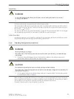
The correct connection of the current and voltage transformers is tested via the protected line using the load
current. For this purpose, connect the line. The load current the line carries must be at least 0.1·
Ι
N
. The load
current should be in-phase or lagging the voltage (resistive or resistive-inductive load). The direction of the
load current must be known. If there is a doubt, network or ring loops should be opened. The line remains
energized during the test.
The direction can be derived directly from the operational measured values. Initially the correlation of the
measured load direction with the actual direction of load flow is checked. In this case the normal situation is
assumed whereby the forward direction (measuring direction) extends from the busbar towards the line (see
the following Figure).
P positive, if active power flows into the line,
P negative, if active power flows towards the busbar,
Q positive, if reactive power flows into the line,
Q negative, if reactive power flows toward the busbar.
3.3.7
Mounting and Commissioning
3.3 Commissioning
216
SIPROTEC 4, 7VK61, Manual
C53000-G1176-C159-5, Edition 05.2018
Содержание SIPROTEC 4 7VK61
Страница 8: ...8 SIPROTEC 4 7VK61 Manual C53000 G1176 C159 5 Edition 05 2018 ...
Страница 10: ...10 SIPROTEC 4 7VK61 Manual C53000 G1176 C159 5 Edition 05 2018 ...
Страница 16: ...16 SIPROTEC 4 7VK61 Manual C53000 G1176 C159 5 Edition 05 2018 ...
Страница 176: ...176 SIPROTEC 4 7VK61 Manual C53000 G1176 C159 5 Edition 05 2018 ...
Страница 224: ...224 SIPROTEC 4 7VK61 Manual C53000 G1176 C159 5 Edition 05 2018 ...
Страница 264: ...264 SIPROTEC 4 7VK61 Manual C53000 G1176 C159 5 Edition 05 2018 ...
Страница 270: ...270 SIPROTEC 4 7VK61 Manual C53000 G1176 C159 5 Edition 05 2018 ...
Страница 276: ...276 SIPROTEC 4 7VK61 Manual C53000 G1176 C159 5 Edition 05 2018 ...
Страница 346: ...346 SIPROTEC 4 7VK61 Manual C53000 G1176 C159 5 Edition 05 2018 ...


