background image

No.

Information

Type of
Informa-
tion

Comments

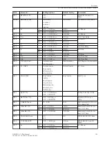
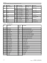
023.2552 I> TRIP

OUT

I> TRIP

023.2553 Ip TRIP

OUT

Ip TRIP

Time Overcurrent Protection for Residual Current

The function and operation of the definite-time overcurrent protection and of the inverse-time overcurrent
protection for residual current is discussed in detail in the section “Time Overcurrent Protection - General”
above (see Section 

2.4.1 General

). The following paragraphs contain the specific information for setting the

overcurrent protection for residual current 

3I0 O/C

.

Setting Notes

General

i

i

NOTE

The first time overcurrent protection for residual current is described in the setting instructions. The param-
eter addresses and message numbers of the second and third time overcurrent protection are described at
the end of the setting instructions under “Additional Time Overcurrent Protection Functions for Residual
Current”.

During configuration of the functional scope (Section 

2.1.3 Functional Scope

) the characteristic type for the

residual current stages is determined under address 122 

DMT/IDMT 3I0

. Only the settings for the character-

istic selected can be performed here. The definite time stages 3

Ι

0>> and 3

Ι

0> are available in all cases.

If a second or third residual overcurrent protection is used, this must be configured accordingly in addresses
134 

DMT/IDMT 3I0 2

 and 136 

DMT/IDMT 3I0 3

.

Each protection function must be assigned to a side of the main protected object or another 3-phase current
measuring location. This can be carried out separately from the phase overcurrent protection (Section

2.1.4 Power System Data 1

 under margin heading “Further 3-phase Protection Functions”). Consider also the

assignment of the measured current inputs of the device against the measuring locations (current transformer
sets) of the power plant (Section 

2.1.4 Power System Data 1

 under margin heading “Assignment of 3-phase

Measuring Locations”).

i

i

NOTE

If the time overcurrent protection is assigned to a side of the main protected object, the current values are
set referred to the rated current of that side 

Ι

/

Ι

NS

. In other cases, current values are set in amps.

In address 2201 

3I0 O/C

, the time overcurrent protection for residual current can be set to 

ON

 or 

OFF

. The

option 

Block relay

 allows to operate the protection but the trip output relay is blocked.

Address 2208A 

3I0 MAN. CLOSE

 determines which of the zero sequence current stages must be activated

instantaneously with a detected manual close. Settings 

3I0>> instant.

 and 

3I0> instant.

 can be set

independently from the selected type characteristics; 

3I0p instant.

 is only possible if one of the inverse

time stages has been configured. The stabilisation does not affect 

3I0>>

. This parameter can only be set with

DIGSI at Additional Settings. For this setting, similar considerations apply as for the phase current stages.
In address 2202 

InRushRest. 3I0

 inrush restraint (inrush restraint with 2nd harmonic) is enabled or disa-

bled. Set 

ON

 if the residual current stage of the time overcurrent protection is applied at the supply side of a

transformer whose starpoint is earthed. Otherwise, retain setting 

OFF

. If you set a very small pickup value,

consider that the inrush restraint function cannot operate below 10 % nominal current (lower limit of
harmonic filtering).

2.4.3

2.4.3.1

Functions

2.4 Time Overcurrent Protection for Phase and Residual Currents

SIPROTEC 4, 7UT6x, Manual

155

C53000-G1176-C230-5, Edition 09.2016

Содержание SIPROTEC 4 7UT6 Series

Страница 1: ...Introduction 1 Functions 2 Mounting and Commissioning 3 Technical Data 4 Ordering Information and Accessories A Terminal Assignments B Connection Examples C Current Transformer Requirements D Default Settings and Protocol dependent Functions E Functions Settings Information F Literature Glossary Index ...

Страница 2: ...We appreciate any suggestions for improvement We reserve the right to make technical improvements without notice Document Version 4 04 00 Release date 09 2016 Copyright Copyright Siemens AG 2016 All rights reserved The reproduction transmission or use of this document or its contents is not permitted without express written authority Offenders will be liable for damages All rights reserved particu...

Страница 3: ...n electrical installations and power plants Applicability of this Manual This manual applies to SIPROTEC 4 Differential Protection 7UT6x Firmware Version V4 67 Indication of Conformity This product complies with the directive of the Council of the European Communities on the approximation of the laws of the Member States relating to electromagnetic compatibility EMC Council Directive 2004 108 EEC ...

Страница 4: ...Information is highlighted and illustrated as follows according to the degree of danger DANGER GEFAHR bedeutet dass Tod oder schwere Verletzungen eintreten werden wenn die angegebenen Maßnahmen nicht getroffen werden Beachten Sie alle Hinweise um Tod oder schwere Verletzungen zu vermeiden Danger indicates that death severe personal injury or substantial material damage will result if proper precau...

Страница 5: ...mation which may be output by the relay or required from other devices or from the switch gear are marked in a monospace type style in quotation marks Deviations may be permitted in drawings and tables when the type of designator can be obviously derived from the illustration The following symbols are used in drawings Device internal logical input signal Device internal logical output signal Inter...

Страница 6: ...tor name Timer pickup delay T example adjustable with setting address and parameter designator name Timer dropout delay T example non adjustable Dynamic triggered pulse timer T monoflop Static memory SR flipflop with setting input S resetting input R output Q and inverted output Q setting input dominant Static memory RS flipflop with setting input S resetting input R output Q and inverted output Q...

Страница 7: ...ons Sides 68 2 1 4 4 Circuit Breaker Data 71 2 1 4 5 Settings 72 2 1 4 6 Information List 84 2 1 5 Setting Groups 85 2 1 5 1 Purpose of Setting Groups 85 2 1 5 2 Setting Notes 85 2 1 5 3 Settings 85 2 1 5 4 Information List 85 2 1 6 Power System Data 2 86 2 1 6 1 Setting Notes 86 2 1 6 2 Settings 88 2 1 6 3 Information List 89 2 2 Differential Protection 92 2 2 1 Functional Description of the Diff...

Страница 8: ...Overcurrent Protection for Residual Current 155 2 4 3 1 Setting Notes 155 2 4 3 2 Settings 159 2 4 3 3 Information List 160 2 5 Time Overcurrent Protection for Earth Current 161 2 5 1 General 161 2 5 2 Definite Time Instantaneous Overcurrent Protection 161 2 5 3 Inverse Time Overcurrent Protection 163 2 5 4 Manual Close Command 165 2 5 5 Dynamic Cold Load Pickup 165 2 5 6 Inrush Restraint 165 2 5 ...

Страница 9: ...ection 218 2 11 1 Functional Description 218 2 11 2 Setting Notes 219 2 11 3 Settings 222 2 11 4 Information List 222 2 12 Reverse Power Protection 224 2 12 1 Functional Description 224 2 12 2 Setting Notes 225 2 12 3 Settings 227 2 12 4 Information List 228 2 13 Forward Power Supervision 229 2 13 1 Functional Description 229 2 13 2 Setting Notes 230 2 13 3 Settings 232 2 13 4 Information List 232...

Страница 10: ...e Failure Monitoring 262 2 19 3 2 Setting Notes 265 2 19 3 3 Settings 266 2 19 3 4 Information List 266 2 19 4 Malfunction Responses of the Monitoring Functions 268 2 19 4 1 Summary of the most important Monitoring Functions 268 2 19 5 Parameterisation Error 270 2 20 Function Control 271 2 20 1 Pickup Logic for the Entire Device 271 2 20 2 Tripping Logic for the Entire Device 271 2 21 Disconnectio...

Страница 11: ...es 301 2 23 1 Demand Measurement Setup 301 2 23 1 1 Setting Notes 301 2 23 1 2 Settings 302 2 23 2 Min Max Measurement Setup 302 2 23 2 1 Setting Notes 302 2 23 2 2 Settings 302 2 23 2 3 Information List 302 2 24 Command Processing 303 2 24 1 Control Authorization 303 2 24 1 1 Type of Commands 303 2 24 1 2 Sequence in the Command Path 303 2 24 1 3 Interlocking 304 2 24 1 4 Recording and Acknowledg...

Страница 12: ...Final Preparation of the Device 393 4 Technical Data 395 4 1 General 396 4 1 1 Analogue Inputs 396 4 1 2 Auxiliary Voltage 396 4 1 3 Binary Inputs and Outputs 397 4 1 4 Frequency Measurement via the Positive Phase sequence Voltage U1 398 4 1 5 Communications Interfaces 399 4 1 6 Electrical Tests 403 4 1 7 Mechanical Tests 405 4 1 8 Climatic Stress Test 405 4 1 9 Service Conditions 406 4 1 10 Const...

Страница 13: ... for 3 Measuring Locations 474 A 3 1 1 3 Differential Protection 7UT633 and 7UT635 for 3 to 5 measuring locations 477 A 4 Accessories 480 B Terminal Assignments 483 B 1 Panel Flush and Cubicle Mounting 484 B 2 Panel Surface Mounting 494 C Connection Examples 505 C 1 Current Transformer Connection Examples 506 C 2 Voltage Transformer Connection Examples 519 C 3 Assignment of Protection Functions to...

Страница 14: ...F 4 Group Alarms 654 F 5 Measured Values 656 Literature 665 Glossary 667 Index 677 Table of Contents 14 SIPROTEC 4 7UT6x Manual C53000 G1176 C230 5 Edition 09 2016 ...

Страница 15: ...roduced in this section An overview of the devices is presented in their application characteristics and scope of functions 1 1 Overall Operation 16 1 2 Application Scope 19 1 3 Characteristics 21 1 SIPROTEC 4 7UT6x Manual 15 C53000 G1176 C230 5 Edition 09 2016 ...

Страница 16: ...s MI transform the currents and voltages derived from the instrument transformers and match them to the internal signal levels for processing in the device Depending on the version the device features between 8 current inputs 7UT612 12 current inputs 7UT613 7UT633 and 16 current inputs 7UT635 Three current inputs are provided for the input of the phase currents at each end of the protected zone me...

Страница 17: ...and control functions are processed in the μC microcomputer system In particular the following is included filtering and conditioning of measured signals continuous monitoring of measured signals monitoring of the pickup conditions of the individual protective functions Conditioning of the measured signals i e conversion of currents according to the connection group of the protected transformer wh...

Страница 18: ...tions A serial service interface can likewise make communication via PC with the device possible by using DIGSI This port is especially well suited for the fixed wiring of the devices to the PC or operation via a modem All data can be transferred to a central control or monitoring system via the serial system port This interface may be provided with various protocols and physical transmission sche...

Страница 19: ...an be installed in order to allow a busbar protection for up to 7 9 or 12 feeders with one single 7UT6x relay Where not all analog measuring inputs are needed for the measured values of the protected object the remaining inputs can be used for other independent measurement or protection tasks If a 7UT635 with 5 threephase measuring inputs is used for instance on a three winding transformer the two...

Страница 20: ...means of flexible functions For up to 12 such functions you determine yourself which measuring quantities to process and how to process them and also which reactions the device is to trigger when settable limit values are overor undershot Thus you can for instance create further time overcurrent protection functions and process voltages powers or symmetrical components One can configure the calcul...

Страница 21: ...ation of trans formers using a further harmonic 3rd or 5th harmonic Insensitivity to DC components and current transformer saturation High level of stability even with different degrees of current transformer saturation High speed instantaneous trip in case of high current transformer faults Independent of the conditioning of the starpoint s of the power transformer Adjustable to the conditioning ...

Страница 22: ...estricted earth fault protection functions possible only 7UT613 63x High impedance Differential Protection Highly sensitive fault current detection using a common external burden resistor Short tripping time Insensitive against DC components and current transformer saturation High stability with optimum matching Suitable for earth fault detection on earthed generators motors shunt reactors and tra...

Страница 23: ...detection Can be assigned to the normal 1 phase current input or to the highly sensitive current input Suitable for detection of very small current e g for high impedance unit protection or tank leakage protection Suitable for detection of any desired AC voltage using an external series resistor e g for high impedance unit protection External blocking facility for any stage Unbalanced Load Protect...

Страница 24: ...stage with external criteria e g with closed emergency tripping Forward power supervision only 7UT613 and 7UT633 Real power calculation from positive sequence components Supervision of overvoltage P or undervoltage P of power with individually adjustable power limits Short operating time or exact calculation of the active power via 16 cycles Automatic blocking of stage P for recognised measured vo...

Страница 25: ...tput relays LEDs and via serial system interfaces to central control and data storage facilities Flexible functions only 7UT613 63x Up to 12 individually configurable protection or monitoring functions Input quantities can be selected from all the connected 3 phase or 1 phase measured quantities Also possible from the measured or combined input quantities symmetrical components power compo nents f...

Страница 26: ... current inputs Blocking of the differential protection system in case of inconsistent settings which could lead to a malfunction Trip circuit supervision is possible Broken wire supervision for the secondary CT circuits with fast phase segregated blocking of the differen tial protection functions and the unbalanced load protection in order to avoid spurious tripping Further Functions Battery buff...

Страница 27: ...Dynamic Cold Load Pickup for Time Overcurrent Protection 172 2 7 Single Phase Time Overcurrent Protection 177 2 8 Unbalanced Load Protection 187 2 9 Thermal Overload Protection 200 2 10 RTD Boxes for Overload Detection 211 2 11 Overexcitation Protection 218 2 12 Reverse Power Protection 224 2 13 Forward Power Supervision 229 2 14 Undervoltage Protection 233 2 15 Overvoltage Protection 236 2 16 Fre...

Страница 28: ...e device in Section 2 1 4 Power System Data 1 of the properties of the main protected object Object properties include the ratings and in the case of transformers the starpoint treatment vector group and where applicable the auto transformer winding Section 2 1 4 Power System Data 1 also deals with the CT data which must be set to ensure that the currents acquired at the various measuring location...

Страница 29: ...ze Internal Real Time Clock 5 Reset LED SP Reset LED 15 Test mode SP Test mode 16 DataStop SP Stop data transmission 51 Device OK OUT Device is Operational and Protecting 52 ProtActive IntSP At Least 1 Protection Funct is Active 55 Reset Device OUT Reset Device 56 Initial Start OUT Initial Start of Device 67 Resume OUT Resume 69 DayLightSavTime OUT Daylight Saving Time 70 Settings Calc OUT Setting...

Страница 30: ...d during configuration or interaction between functions may be adjusted Functions not to be used in the actual 7UT6x device can thus be masked out Example for the configuration of the scope of functions 7UT6x devices are intended to be used for busbars and transformers Overload protection should only be applied on transformers If the device is used for busbars this function is set to Disabled for ...

Страница 31: ...ring locations current transformers are available Normal Power transformers with separate windings are set as PROT OBJECT 3 phase transf regardless of the number of windings vector groups and the earthing conditions of the starpoints This is also valid if a neutral earthing reactor is situated within the protected zone If the differential protection shall cover a generator or motor and a unit conn...

Страница 32: ...uts of the device 7UT612 allows up to 2 7UT613 and 7UT633 allow a maximum number of 3 7UT635 a maximum of 5 measuring locations This setting applies also for short lines which are terminated by sets of current transformers at each terminal Short means in this context that the current transformer connections from the CTs to the device do not cause impermissible load to the current transformers The ...

Страница 33: ... overcurrent protection under address 130 the same applies under address 132 for DMT IDMT Phase3 The selected options may be the same or different for the three time overcurrent protection functions Time overcurrent protection for zero sequence currents The type of characteristics used for the zero sequence residual overcurrent time protection can be set in address 122 DMT IDMT 3I0 The same option...

Страница 34: ... phase busbar protection address 105 PROT OBJECT 1ph Busbar is not possible If the overload protection is not required set to Disabled Furthermore the following is available Overload protection with a thermal replica according to IEC 60255 8 Overload protection with calculation of hot spot temperature and the aging rate according to IEC 60354 Overload protection using a thermal replica with ambien...

Страница 35: ...ent inputs and voltages are connected This protection is not appli cable for single phase busbar protection address 105 PROT OBJECT 1ph Busbar For further details see Section 2 11 Overexcitation Protection Reverse Power Protection The reverse power protection only for devices with measuring voltage inputs address 150 REVERSE POWER primarily protects a turbine generator unit on failure of notenergy...

Страница 36: ...ll Measuring Location Disconnection The disconnection of the measuring location address 180 DISCON MEAS LOC is a help function for commis sioning and revision works in the system Measured Value Monitoring The different methods of measured value monitoring address 181 M V SUPERV are set out in detail in Section 2 19 1 Measurement Supervision Voltages can of course also be monitored if the device pr...

Страница 37: ...lt protection 2 117 COLDLOAD PICKUP Disabled Enabled Disabled Cold Load Pickup 120 DMT IDMT Phase Disabled Definite Time TOC IEC TOC ANSI User Defined PU User def Reset Disabled DMT IDMT Phase 122 DMT IDMT 3I0 Disabled Definite Time TOC IEC TOC ANSI User Defined PU User def Reset Disabled DMT IDMT 3I0 124 DMT IDMT Earth Disabled Definite Time TOC IEC TOC ANSI User Defined PU User def Reset Disable...

Страница 38: ...LOAD Disabled Definite Time TOC IEC TOC ANSI DT thermal Disabled Unbalance Load Negative Sequence 142 THERM OVERLOAD Disabled th rep w o sen th repl w sens IEC354 Disabled Thermal Overload Protection 143 OVEREXC PROT Disabled Enabled Disabled Overexcitation Protection U f 144 THERM OVERLOAD2 Disabled th rep w o sen th repl w sens IEC354 Disabled Thermal Overload Protection 2 150 REVERSE POWER Disa...

Страница 39: ...ion 186 EXT TRIP 1 Disabled Enabled Disabled External Trip Function 1 187 EXT TRIP 2 Disabled Enabled Disabled External Trip Function 2 190 RTD BOX INPUT Disabled Port C Port D Disabled External Temperature Input 191 RTD CONNECTION 6 RTD simplex 6 RTD HDX 12 RTD HDX 6 RTD simplex Ext Temperature Input Connec tion Type FLEXIBLE FcT 1 12 Flexible Function 01 Flexible Function 02 Flexible Function 03...

Страница 40: ...bjects1 for busbar 1 phase Voltage 3 phase Voltage 1 phase Current 3 phase1 Current auxiliary Strom 1 phase Current auxiliary 1 phase sensitive2 1 phase sensitive2 7UT612 2 2 1 7 2 1 7UT613 3 3 1 9 3 1 1 1 7UT633 3 3 1 9 3 1 1 1 7UT635 5 1 1 4 4 2 12 4 2 1 also applicable for single phase power transformers 2 selectable contained in the number of 1 phase inputs Terminology The topology of the prot...

Страница 41: ...e processed by the differential protection example inclusion of the starpoint current in the differential current The currents of the non assigned auxiliary inputs can be processed by other protection functions example detection of a tank leakage current by the single phase overcurrent protection or they can also be combined with other non assigned 3 phase measuring points example restricted earth...

Страница 42: ...e differential protection function for the formation of the differential current For the restricted earth fault protection operating at the higher voltage winding it can supply the starpoint current of side 1 The auxiliary measuring location X4 is not assigned to the main protected object because it is not required by the differential protection It is a non assigned measuring location which is use...

Страница 43: ...in protected object side 1 M3 Measuring location assigned to the main protected object side 2 M4 Measuring location assigned to the main protected object side 3 Measuring locations 3 phase non assigned M5 Measuring location not assigned to the main protected object associated with the neutral reactor Auxiliary measuring locations 1 phase X4 Measuring location not assigned to the main protected obj...

Страница 44: ...g locations ΙL1M1 ΙL2M1 ΙL3M1 in single phase transformers ΙL2M1 is omitted The topological data can be altered only with a PC using DIGSI Global Data for 3 Phase Measuring Locations Determine the total number of 3 phase current measuring locations connected current transformer sets which are connected to the device Enter this number in address 211 No Conn MeasLoc number of meas uring locations co...

Страница 45: ... auto transformers must always be defined as S1 and S2 A third side may be present if the compensation winding is dimensioned as power winding tertiary winding and accessible Figure 2 5 In this example we have 3 sides and 4 assigned measuring locations During para metrization of the autotransformer one must always start with the auto winding topologie spartransformator tertiaerwicklung ausgleich 2...

Страница 46: ...ives an example of a 3 phase presentation In this example we have 3 sides and 3 assigned three phase measuring locations The auto connected winding terminals form the sides S1 full winding and S2 tap with the assigned 3 phase measuring locations M1 and M2 As the delta winding functions both as the tertiary winding and the compensation winding it is the third side S3 with measuring location M3 The ...

Страница 47: ... via each winding has been selected then the example of Figure 2 7 applies Besides the common winding terminals of the sides S1 full winding and S2 tap with the assigned 3 phase measuring locations M1 and M2 one more side S3 is defined at the starpoint terminals with the 3 phase measuring location M3 In this way a current comparison can be realised over each of the three transformer windings i e e...

Страница 48: ...hase Sides S1 High voltage side of the auto connected winding of the main protected object S2 Low voltage side tap of the auto connected winding of the main protected object S3 Starpoint side of the auto connected winding of the main protected object Measuring locations 3 phase assigned M1 Measuring location assigned to the main protected object side 1 M2 Measuring location assigned to the main pr...

Страница 49: ...M1 M2 i e the 2 measuring locations are assigned M1 to side S1 M2 to side S2 Since no other possibilities exist there are no further options Address 221 ASSIGNM 3M 2S appears if 3 assigned measuring locations address 212 have been selected for 2 sides address 213 The following options are possible M1 M2 M3 i e the 3 measuring locations are assigned M1 and M2 to side S1 M3 to side S2 M1 M2 M3 i e t...

Страница 50: ...ations are assigned M1 to side S1 M2 and M3 and M4 to side S2 M5 to side S3 M1 M2 M3 M4 M5 i e the 5 measuring locations are assigned M1 to side S1 M2 to side S2 M3 and M4 and M5 to side S3 Address 228 ASSIGNM 5M 4S appears if 5 assigned measuring locations address 212 have been selected for 4 sides address 213 The following options are possible M1 M2 M3 M4 M5 i e the 5 measuring locations are ass...

Страница 51: ... changed For the sides 3 and 4 alternatives exist If the auto transformer provides another tap the side thereof is declared as aauto connected In the example in Figure 2 6 is for a PROT OBJECT Autotransf the side S3 the tertiary winding thus the accessible and load capable compensation winding In this example the setting would be Address 243 SIDE 3 compensation This option is only possible for PRO...

Страница 52: ...to side S2 For the auto transformer it is therefore irrelevant which voltage side of the common winding start of winding or any tap the starpoint current is assigned to 2nd case For this case the same considerations apply as for the 1st case In the case of generators motors or shunt reactors select the terminal side You can also use in the 2nd case a measuring location that is not assigned to the ...

Страница 53: ...he setting 1A 5A input unchanged In 7UT635 the input ΙX3 can be used as a high sensitivity input provided that it is not used for a fifth 3 phase measuring location i e that only four 3 phase measuring locations are needed In this case set address 255 AUX CT IX3 TYPE sensitiv input if ΙX3 is used as a high sensitivity input The input ΙX4 is always available as a single phase input in 7UT635 and ca...

Страница 54: ...n function is used you must choose and connect a voltage that is suitable for over flux protection For transformers it must be a non regulated side since a proportional relationship between the quotient U f and the iron core induction B is found only there If for example in Figure 2 8 the winding at side 1 has a voltage controller Side 2 must be selected For the power protection functions it is im...

Страница 55: ...w specify in the device how the connected 1 phase voltage should be interpreted This is done at address 263 VT U4 TYPE Set Udelta transf if the voltage assigned acc to address 262 is a displacement voltage It can also be any phase to earth voltage e g UL1E transform or a phase to phase voltage e g UL12 transform If U4 is connected to a voltage which is assigned to no side or measuring location set...

Страница 56: ... requested here They will be entered at a later date margin heading Object Data for Further Protected Objects For side 1 the device needs the following information The primary rated voltage UN in kV phase to phase under address 311 UN PRI SIDE 1 The primary rated apparent power under address 312 SN SIDE 1 Note that the power ratings of the windings of power transformers with more than 2 windings m...

Страница 57: ... the transformer data of the transformer windings at side 2 The vector group numeral states the phase displacement of side 2 against the reference winding side 1 It is defined according to IEC as the multiple of 30 If the higher voltage side is the reference side 1 you may take the data directly from the vector group designation For instance for a transformer Yd5 is CONNECTION S2 D and VECTOR GRP ...

Страница 58: ...red to match the vector group and the different rated winding currents The currents are converted such that the sensitivity of the protection always refers to the power rating of the transformer In case of different rating of the windings the rated apparent power of the most powerful winding is the rated apparent power of the transformer In general no circuits are required for matching of the vect...

Страница 59: ...d main object as defined in the topology No data of the sides which are not assigned are requested here They will be entered at a later date margin heading Object Data for Further Protected Objects Under address 372 I PRIMARY OP S1 set the rated primary current of the feeder 1 As mentioned above the sides and the assigned measurement locations are identical for busbars The same considerations appl...

Страница 60: ...Protected Objects The object data described in the previous paragraphs relate to the main protected object whose sides and measuring locations have been assigned according to Section 2 1 4 Power System Data 1 If you have defined further protected objects in your topology a number of non assigned measuring locations will be left The rated values of these are requested now The considerations concern...

Страница 61: ...ry starpoint position of the current transformer sets In address 512 IN PRI CT M1 the rated primary current of the current transformer set of measuring location M1 is set in address 513 IN SEC CT M1 the rated secondary current Please make sure that the sides were defined correctly see Section 2 1 4 Power System Data 1 margin heading Assignment of 3 phase Measuring Locations Please also make sure t...

Страница 62: ...ly those addresses will appear during setting which are available in the actual device version Measuring Location 2 Address 521 STRPNT OBJ M2 starpoint position of CTs for measuring location M2 Address 522 IN PRI CT M2 prim rated current of CTs for measuring location M2 Addrese 523 IN SEC CT M2 sec nominal current CT for measuring location M2 Functions 2 1 General 62 SIPROTEC 4 7UT6x Manual C53000...

Страница 63: ...ed object the opposite setting is to be selected for side 2 STRPNT OBJ M2 NO anlagendaten beispiel3 020904 st 1 en_GB Figure 2 14 Current transformer starpoints in transverse differential protection example Current Transformer Data for Single phase Busbar Protection The operational nominal currents of each feeder already have been set under margin heading Object Data with Busbars 1 phase Connectio...

Страница 64: ... starpoints example for phase L1 of a busbar with 3 feeders The parameters for the individual feeders are Feeder 1 Address 561 STRPNT BUS I1 transformer starpoint versus busbar for feeder 1 Address 562 IN PRI CT I1 rated primary transformer current for feeder 1 Address 563 IN SEC CT I1 rated secondary transformer current for feeder 1 Feeder 2 Address 571 STRPNT BUS I2 transformer starpoint versus ...

Страница 65: ...ormer starpoint versus busbar for feeder 10 Address 652 IN PRI CT I10 rated primary transformer current for feeder10 Address 653 IN SEC CT I10 rated secondary transformer current for feeder 10 Feeder 11 Address 661 STRPNT BUS I11 transformer starpoint versus busbar for feeder 11 Address 662 IN PRI CT I11 rated primary transformer current for feeder 11 Address 663 IN SEC CT I11 rated secondary tran...

Страница 66: ...1 phase current input is important for correct function of the differential protection and the restricted earth fault protection If only the magnitude of the current is of interest e g for earth overcurrent protection or single phase overcurrent protection the polarity is irrelevant Even though a high sensitive 1 phase current input has been selected the polarity setting is omitted as it only proc...

Страница 67: ... 802 UN SEC VT SET the secondary rated VT voltage If the reverse power protection with high precision active power measurement is used a correction of the angle faults of the current and voltage transformers is particularly important as in this case a very low active power is computed from a very high apparent power for small cos In other cases absolute compliance with the angle of measured values...

Страница 68: ...luated as currents flowing into the transformer Where an external current flows in via M4 and out again through M3 the sum of ΙM3 ΙM4 0 i e no current flows into the protected object at that point Nevertheless both currents are used for restraint of the differential protection For more details please refer to the description of the differential protection function Section 2 2 Differential Protecti...

Страница 69: ...c tion for zero sequence current and asymmetrical load protection These further protection functions can operate on the main protected object or on a further protected object The possibilities depend on the definitions made in the topology For the main protection object you normally choose one side for which the protection function will be effec tive If in the example shown in Figure 2 2 you want ...

Страница 70: ...it is therefore not reasonable to calculate the temperature rise In this case however a current dependent alarm stage is able to warn of an imminent overload The same applies to the second overload protection that is assigned to a side under address 444 THERM O L 2 AT The overexcitation protection Section 2 11 Overexcitation Protection is only possible for devices with voltage connection and requi...

Страница 71: ...tion Command processing makes also use of the feedback information from the switching devices If for instance the circuit breaker failure protection is used to monitor the reaction of a specific circuit breaker CB the protection device must know the measuring location at which the current flowing through the breaker is acquired and the binary inputs which provide information on the breaker status ...

Страница 72: ...ommand indicated via a binary input you must have selected that logical input indication during the configuration of the binary inputs that corresponds to the side or measuring location to which the protection function is assigned From the internal control the device uses the same switching objects that were selected at the addresses 831 to 840 Example If you have assigned the time overcurrent pro...

Страница 73: ...S M1 M2 M3 M4 M5 M1 M2 M3 M4 M5 M1 M2 M3 M4 M5 M1 M2 M3 M4 M5 M1 M2 M3 M4 M 5 Assignment at 5 assig Meas Loc 2 Sides 227 ASSIGNM 5M 3S M1 M2 M3 M4 M5 M1 M2 M3 M4 M5 M1 M2 M3 M4 M5 M1 M2 M3 M4 M5 M1 M2 M3 M4 M5 M1 M2 M3 M4 M5 M1 M2 M3 M4 M5 Assignment at 5 assig Meas Loc 3 Sides 228 ASSIGNM 5M 4S M1 M2 M3 M4 M5 M1 M2 M3 M4 M5 M1 M2 M3 M4 M5 M1 M2 M3 M4 M5 M1 M2 M3 M4 M5 Assignment at 5 assig Meas L...

Страница 74: ... MeasLoc 3 earth MeasLoc 4 earth Not connected Auxiliary CT IX2 is used as 253 AUX CT IX3 Not connected conn not assig Side 1 earth Side 2 earth Side 3 earth Side 4 earth MeasLoc 1 earth MeasLoc 2 earth MeasLoc 3 earth MeasLoc 4 earth Not connected Auxiliary CT IX3 is used as 254 AUX CT IX4 Not connected conn not assig Side 1 earth Side 2 earth Side 3 earth Side 4 earth Side 5 earth MeasLoc 1 eart...

Страница 75: ...sf VT U4 is used as 270 Rated Frequency 50 Hz 60 Hz 16 7 Hz 50 Hz Rated Frequency 271 PHASE SEQ L1 L2 L3 L1 L3 L2 L1 L2 L3 Phase Sequence 276 TEMP UNIT Celsius Fahrenheit Celsius Unit of temperature measurement 311 UN PRI SIDE 1 0 4 800 0 kV 110 0 kV Rated Primary Voltage Side 1 312 SN SIDE 1 0 20 5000 00 MVA 38 10 MVA Rated Apparent Power of Transf Side 1 313 STARPNT SIDE 1 Earthed Isolated Earth...

Страница 76: ...T SIDE 3 Earthed Isolated Earthed Starpoint of Side 3 is 334 CONNECTION S3 Y D Z Y Transf Winding Connection Side 3 335 VECTOR GRP S3 0 1 2 3 4 5 6 7 8 9 10 11 0 Vector Group Numeral of Side 3 341 UN PRI SIDE 4 0 4 800 0 kV 11 0 kV Rated Primary Voltage Side 4 342 SN SIDE 4 0 20 5000 00 MVA 10 00 MVA Rated Apparent Power of Transf Side 4 343 STARPNT SIDE 4 Earthed Isolated Earthed Starpoint of Sid...

Страница 77: ... 370 UN BUSBAR 0 4 800 0 kV 110 0 kV Rated Primary Voltage Busbar 371 I PRIMARY OP 1 100000 A 200 A Primary Operating Current of Busbar 372 I PRIMARY OP S1 1 100000 A 200 A Primary Operating Current Side 1 373 I PRIMARY OP S2 1 100000 A 200 A Primary Operating Current Side 2 374 I PRIMARY OP S3 1 100000 A 200 A Primary Operating Current Side 3 375 I PRIMARY OP S4 1 100000 A 200 A Primary Operating...

Страница 78: ...A 200 A Primary Operating Current Meas Loc 3 404 I PRIMARY OP M4 1 100000 A 200 A Primary Operating Current Meas Loc 4 405 I PRIMARY OP M5 1 100000 A 200 A Primary Operating Current Meas Loc 5 408 UN PRI M3 0 4 800 0 kV 110 0 kV Rated Primary Voltage Measuring Loc 3 409 UN PRI U4 0 4 800 0 kV 110 0 kV Rated Primary Voltage U4 413 REF PROT AT Side 1 Side 2 Side 3 Side 4 Side 5 auto connected n assi...

Страница 79: ... 427 DMT 1PHASE AT no assig poss AuxiliaryCT IX1 AuxiliaryCT IX2 AuxiliaryCT IX3 AuxiliaryCT IX4 AuxiliaryCT IX1 DMT 1Phase assigned to 430 DMT IDMT Ph2 AT Side 1 Side 2 Side 3 Side 4 Side 5 Measuring loc 1 Measuring loc 2 Measuring loc 3 Measuring loc 4 Measuring loc 5 Side 1 DMT IDMT Phase 2 assigned to 432 DMT IDMT Ph3 AT Side 1 Side 2 Side 3 Side 4 Side 5 Measuring loc 1 Measuring loc 2 Measur...

Страница 80: ... DMT IDMT E2 AT no assig poss AuxiliaryCT IX1 AuxiliaryCT IX2 AuxiliaryCT IX3 AuxiliaryCT IX4 AuxiliaryCT IX1 DMT IDMT Earth 2 assigned to 440 UNBAL LOAD AT Side 1 Side 2 Side 3 Side 4 Side 5 Measuring loc 1 Measuring loc 2 Measuring loc 3 Measuring loc 4 Measuring loc 5 Side 1 Unbalance Load Neg Seq assigned to 442 THERM O L AT Side 1 Side 2 Side 3 Side 4 Side 5 Side 1 Thermal Overload Protection...

Страница 81: ...1A 5A 1A CT Rated Secondary Current Meas Loc 1 521 STRPNT OBJ M2 YES NO YES CT Strpnt Meas Loc 2 in Dir of Object 522 IN PRI CT M2 1 100000 A 2000 A CT Rated Primary Current Meas Loc 2 523 IN SEC CT M2 1A 5A 1A CT Rated Secondary Current Meas Loc 2 531 STRPNT OBJ M3 YES NO YES CT Strpnt Meas Loc 3 in Dir of Object 532 IN PRI CT M3 1 100000 A 2000 A CT Rated Primary Current Meas Loc 3 533 IN SEC CT...

Страница 82: ...ted Secondary Current I3 591 STRPNT BUS I4 YES NO YES CT Starpoint I4 in Direction of Busbar 592 IN PRI CT I4 1 100000 A 200 A CT Rated Primary Current I4 593 IN SEC CT I4 1A 5A 0 1A 1A CT Rated Secondary Current I4 601 STRPNT BUS I5 YES NO YES CT Starpoint I5 in Direction of Busbar 602 IN PRI CT I5 1 100000 A 200 A CT Rated Primary Current I5 603 IN SEC CT I5 1A 5A 0 1A 1A CT Rated Secondary Curr...

Страница 83: ...T I12 1 100000 A 200 A CT Rated Primary Current I12 673 IN SEC CT I12 1A 5A 0 1A 1A CT Rated Secondary Current I12 711 EARTH IX1 AT Terminal Q7 Terminal Q8 Terminal Q7 Earthing electrod IX1 connected to 712 IN PRI CT IX1 1 100000 A 200 A CT rated primary current IX1 713 IN SEC CT IX1 1A 5A 1A CT rated secondary current IX1 721 EARTH IX2 AT Terminal N7 Terminal N8 Terminal N7 Earthing electrod IX2 ...

Страница 84: ...CBaux S4 Einstellmöglichkeiten anwendungsabhängig none Switchgear CBaux at Side 4 835 SwitchgCBaux S5 Einstellmöglichkeiten anwendungsabhängig none Switchgear CBaux at Side 5 836 SwitchgCBaux M1 Einstellmöglichkeiten anwendungsabhängig none Switchgear CBaux at Measuring Loc M1 837 SwitchgCBaux M2 Einstellmöglichkeiten anwendungsabhängig none Switchgear CBaux at Measuring Loc M2 838 SwitchgCBaux M3...

Страница 85: ...dress 103 For the setting of the function parameters each of the required 4 setting groups Group A to Group D must be configured More details on how to navigate between the setting groups to copy and reset setting groups and how to switch over between the setting groups during operation can be found in the 1 SIPROTEC 4 System Manual The preconditions for switching from one setting group to another...

Страница 86: ...asuring Inputs where the voltage measuring location U is assigned to the current measuring location M1 the default setting not reversed is not inverted because the in flowing current into the generator from the starpoint at M1 together with the measured voltage at U results in positive power However if the voltage at U is assigned to the current measuring location M2 P Q sign reversed must be set ...

Страница 87: ... are fed by multiple measuring locations In the 1 phase busbar protection you can set such an open pole current for each of the up to 9 feeders 7UT613 and 7UT633 for 1 phase connection with or without summation CT or 12 feeders 7UT635 with or without summation CT of the busbar The maximum range of possible addresses includes Address 1131 PoleOpenCurr I1 for feeder 1 Address 1132 PoleOpenCurr I2 fo...

Страница 88: ... Pole Open Current Threshold Meas Loc M1 5A 0 20 5 00 A 0 20 A 1122 PoleOpenCurr M2 1A 0 04 1 00 A 0 04 A Pole Open Current Threshold Meas Loc M2 5A 0 20 5 00 A 0 20 A 1123 PoleOpenCurr M3 1A 0 04 1 00 A 0 04 A Pole Open Current Threshold Meas Loc M3 5A 0 20 5 00 A 0 20 A 1124 PoleOpenCurr M4 1A 0 04 1 00 A 0 04 A Pole Open Current Threshold Meas Loc M4 5A 0 20 5 00 A 0 20 A 1125 PoleOpenCurr M5 1...

Страница 89: ... 1 00 A 0 04 A Pole Open Current Threshold AuxiliaryCT1 5A 0 20 5 00 A 0 20 A 1152 PoleOpenCurrIX2 1A 0 04 1 00 A 0 04 A Pole Open Current Threshold AuxiliaryCT2 5A 0 20 5 00 A 0 20 A 1153 PoleOpenCurrIX3 1A 0 04 1 00 A 0 04 A Pole Open Current Threshold AuxiliaryCT3 5A 0 20 5 00 A 0 20 A 1154 PoleOpenCurrIX4 1A 0 04 1 00 A 0 04 A Pole Open Current Threshold AuxiliaryCT4 5A 0 20 5 00 A 0 20 A Info...

Страница 90: ...an Clos Det M2 OUT Manual close signal meas loc 2 detected 30072 Man Clos Det M3 OUT Manual close signal meas loc 3 detected 30073 Man Clos Det M4 OUT Manual close signal meas loc 4 detected 30074 Man Clos Det M5 OUT Manual close signal meas loc 5 detected 30075 Man Clos Det S1 OUT Manual close signal side 1 is detected 30076 Man Clos Det S2 OUT Manual close signal side 2 is detected 30077 Man Clo...

Страница 91: ...8 VI Primary fault current I8 30276 I9 VI Primary fault current I9 30277 I10 VI Primary fault current I10 30278 I11 VI Primary fault current I11 30279 I12 VI Primary fault current I12 30351 ManualClose M1 SP Manual close signal measurement loc 1 30352 ManualClose M2 SP Manual close signal measurement loc 2 30353 ManualClose M3 SP Manual close signal measurement loc 3 30354 ManualClose M4 SP Manual...

Страница 92: ...zone and leaves it again on the other side A difference in currents is a clear indication of a fault within this section If the actual current transformation ratio is the same the secondary windings of the current transformers CT1 and CT2 at the sides of the protected object can be connected to form a closed electric circuit with a secondary current I a measuring element M which is connected to th...

Страница 93: ...bjects with two terminals a restraining quantity is normally derived from the current difference Ι1 Ι2 or from the arithmetical sum Ι1 Ι2 Both methods are equal in the relevant ranges of the stabilisation characteristics For protected objects with more than two ends such as multi winding transformers busbars etc only the arithmetical sum method is possible The latter method is used in 7UT6x for al...

Страница 94: ...following applies Ι2 Ι1 außerdem ist Ι2 Ι1 Ιdiff Ι1 Ι2 Ι1 Ι1 2 Ι1 Ιstab Ι1 Ι2 Ι1 Ι1 2 Ι1 Tripping effect Ιdiff and restraint value Ιstab are equal and correspond to the total fault Internal short circuit fed from one side only The following applies Ι2 0 Ιdiff Ι1 Ι2 Ι1 0 Ι1 Ιstab Ι1 Ι2 Ι1 0 Ι1 Tripping quantity Ιdiff and restraint value Ιstab are equal and correspond to the single sided fault curre...

Страница 95: ...tant of CT saturation B a differential quantity is produced and the restraint quantity is reduced In consequence the operating point Ιdiff Ιstab may move into the tripping area C In contrast the operating point moves immediately along the fault characteristic D when an internal fault occurs since the restraint stabilisation current will barely be higher than the differential current Current transf...

Страница 96: ...it exist an another method called Current Waveform Analysis CWA If the CWA function is enabled and this algorithm detects a asymmetric current waveform then the tripping is blocked by the differential current threshold Steady state overexcitation is characterised by odd harmonics The 3rd or 5th harmonic is suitable to detect overexcitation As the third harmonic is often eliminated in transformers ...

Страница 97: ...ject is switched in As soon as the restraint current of one phase has undershot a settable value I REST STARTUP the increase of the pickup value is activated As the restraint current is twice the through flowing current in normal operation its undershooting of that threshold is a criterion for detecting that the protected object is not energised The pickup value I DIFF and the other branches of th...

Страница 98: ...e to add on stabilisation startup or DC current detec tion Fault Detection Dropout Normally a differential protection does not need a pickup since the condition for a fault detection is iden tical to the trip condition Like all SIPROTEC 4 devices however the differential protection feature of the 7UT6x has a pickup that is the starting point for a number of subsequent activities The pickup marks t...

Страница 99: ...ms a harmonic analysis approx 1 cycle to check the restraint conditions as the case may be Otherwise tripping occurs as soon as the tripping conditions are fulfilled For special cases the trip command can be delayed The following logic diagram illustrates the tripping logic dar Functions 2 2 Differential Protection SIPROTEC 4 7UT6x Manual 99 C53000 G1176 C230 5 Edition 09 2016 ...

Страница 100: ...ions are no longer fulfilled either If a trip command has not been initiated the fault is considered ended on dropout If a trip command had been initiated it is maintained for the minimum command duration set in the general device data for all protection functions see also 2 1 4 Power System Data 1 The trip command will not be reset until all other dropout conditions mentioned above are fulfilled ...

Страница 101: ...rents of the current trans formers deviate from the nominal currents of the power transformer sides the secondary currents are multi plied with the factors k1 and k2 After this matching equal current magnitudes are achieved at both sides under nominal conditions of the power transformer betraganpassung bsp 2wick trans280503 st 1 en_GB Figure 2 26 Magnitude matching example of a two winding power t...

Страница 102: ...ible In this regard the conditioning of the starpoint s of the power transformer is also essential Non earthed Transformer Starpoint Figure 2 28 illustrates an example for a power transformer Yd5 wye delta with 150 phase displacement without any earthed starpoint The figure shows the windings above and the vector diagrams of symmetrical currents below The general form of the matrix equation is dif...

Страница 103: ... ential quantity because they pass the measuring points from outside Even higher earth fault sensitivity during internal earth fault is possible by means of the time overcurrent protection for zero sequence currents Section 2 4 1 General and or the single phase time overcurrent protection Section 2 7 Single Phase Time Overcur rent Protection Earthed Starpoint Differential protection makes use of t...

Страница 104: ...ents is thus not possible because ΙSP is missing In order to avoid false formation of the differential current the zero sequence current must be eliminated from the line currents ΙL3 3 Ι0 Figure 2 30 shows an example of a YNd5 vector group with earthed starpoint on the Y side In Figure 2 30 on the left side the zero sequence currents cancel each other because of the calculation of the current diff...

Страница 105: ...ected transformer with a neutral earthing reactor within the protected zone The disadvantage of elimination of the zero sequence current is that the protection becomes less sensitive factor 2 3 because the zero sequence current amounts to 1 3 in case of an earth fault in the protected area Therefore elimination is suppressed in case the starpoint is not earthed see Figure 2 28 or the starpoint cur...

Страница 106: ...he externally located earth faults by the sum of the starpoint current In case of internally located earth fault the full sensi tivity of the differential protection is ensured For consideration of the earth fault current the advanced parameter diff protection with measured earth current side x must be switched on addresses 1211 DIFFw IE1 MEAS to 1215 DIFFw IE5 MEAS YES Increased earth fault sensi...

Страница 107: ...ement between the windings can only be 0 or 180 matching is relevant only with respect to the treatment of the zero sequence current besides magnitude matching If a Starpoint of the protected transformer winding is not earthed left in Figure 2 34 the phase currents can directly be used If the starpoint is earthed figure Figure 2 34 right side the zero sequence current must be eliminated unless it ...

Страница 108: ...tors The protected zone is limited by the sets of current transformers at each side of the protected object On generators and motors the CT are installed in starpoint connection at the terminal side Since the current direction is normally defined as positive in the direction of the protected object for differential protection schemes the definitions shown in Figure 2 36 diff generator laengsdiff 0...

Страница 109: ...erential protection see Section 2 7 Single Phase Time Overcurrent Protection Differential Protection for Shunt Reactors If current transformers are available for each phase at both sides of a shunt reactor the same considerations apply for series reactors In most cases current transformers are installed in the lead phases and in the starpoint connection see Figure 2 38 In this case comparison of t...

Страница 110: ...phase branch points or mini busbars with 2 terminals to be protected 7UT613 and 7UT633 allow 3 terminals and 7UT635 up to 5 terminals Figure 2 41 shows the example of a busbar with 4 feeders diff ss stromdefinition 020926 rei 1 en_GB Figure 2 39 Definition of current direction at a branch point busbar with 2 feeders diff leitung stromdefinition 020926 rei 1 en_GB Figure 2 40 Definition of current ...

Страница 111: ...tial Protection for Busbars Dependent on the ordered model 7UT6x provides 7 9 or 12 current inputs of equal design This allows for a single phase differential current busbar protection for up to 7 or 9 or 12 feeders There are two connection possibilities One 7UT6x is used for each phase Each phase of all busbar feeders is connected to one phase dedicated device 7UT6x The three phase currents of ea...

Страница 112: ... be performed in the summation transformer connections if the feeder CTs have different nominal currents The output of the summation transformers is normally designed for IM 100 mA at symmetrical rated busbar current The nominal current at the device input ΙN Obj 100 mA is applicable diff ssmischwandler 020926 rei 1 en_GB Figure 2 43 Busbar protection with connection via summation current transfor...

Страница 113: ...current diff ssmischwandler l1l3e stroeme 020926 rei 1 en_GB Figure 2 45 Summation of the currents in the summation transformer on connection L1 L3 E For the connection L1 L3 E see Figure 2 44 the weighting factors W of the summation currents ΙM for the various fault conditions and the ratios to that given by the three phase symmetrical faults are shown in Table 2 5 On the right hand side is the c...

Страница 114: ...tion L1 L2 L3 with decreased earth fault sensitivity diff ssmischwandler l1l2l3 stroeme 020926 rei 1 en_GB Figure 2 47 Summation of the currents in the summation transformer on connection L1 L2 L3 Table 2 6 Fault conditions and weighting factors for the CT connection L1 L2 L3 Fehler W W 3 Ι1 for ΙM 100 mA L1 L2 L3 sym L1 L2 L2 L3 L3 L1 L1 E L2 E L3 E 3 1 2 1 2 1 3 1 00 0 58 1 15 0 58 1 15 0 58 1 7...

Страница 115: ...it of the current transformers When during normal load conditions a differential current is detected in the order of the load current of a feeder this indicates a missing secondary current i e a fault in the secondary current leads short circuit or open circuit This condition is annunciated with time delay The differential protection is blocked at the same time Feeder Current Guard With busbars a ...

Страница 116: ...onsidered by the differential protection In auto transformers the earth current flowing in the winding can be considered even if a complete three phase CT set has been installed as illustrated in Figure 2 6 where instead of measuring location Z3 also the three phase currents can be connected to a three phase measuring input of the device The device then calcu lates the sum of the three currents an...

Страница 117: ...ormer sets are of similar design A higher value above rated current should be selected for lines and busbars Higher measuring tolerances must be expected if the rated currents of the current transformers differ extensively from the rated current of the protected object or if there are multiple measuring locations Besides the threshold I DIFF is a second threshold available In case of exceeding thi...

Страница 118: ... restraint This parameter can only be set with DIGSI at Additional Settings Delay Times In special cases it may be advantageous to delay the trip signal of the differential protection For this an addi tional delay can be set The delay time 1226 T I DIFF is started if an internal fault in the protected object has been detected by the I DIFF stage and the trip characteristic 1236 T I DIFF is the tim...

Страница 119: ...e all phases will be blocked in this case the same setting as for 1262 T ADD ON STAB is advisable When set to the crossblock function is always effective Harmonic Restraint Restraint with harmonic content is available only when the device is used as transformer protection i e the PROT OBJECT address 105 is a 3 phase transf or 1 phase transf orAutotransf or Autotr node This function is also used fo...

Страница 120: ...ation of a power transformer a differential current may occur due to magnetizing currents cause by increased voltage and or decreased frequency Inrush current may result in a mal operation of the differential protection Typical for a transformer energizing process is the occurrence of flat areas in the current see following figure If these flat areas occur in all 3 phases at the same time this is ...

Страница 121: ... always refer to the rated current of the relevant side of the main protected object Settings Addresses which have an appended A can only be changed with DIGSI under Additional Settings Addr Parameter Setting Options Default Setting Comments 1201 DIFF PROT OFF ON Block relay OFF Differential Protection 1205 INC CHAR START OFF ON OFF Increase of Trip Char During Start 1206 INRUSH 2 HARM OFF ON ON I...

Страница 122: ...MAX 0 0 180 0 sec 5 0 sec Maximum Permissible Starting Time 1261A I ADD ON STAB 2 00 15 00 I InO 4 00 I InO Pickup for Add on Stabilization 1262A T ADD ON STAB 2 250 Cycle 15 Cycle Duration of Add on Stabilization 1263A CROSSB ADD ON 2 1000 Cycle 0 15 Cycle Time for Cross blocking Add on Stabiliz 1271 2 HARMONIC 10 80 15 2nd Harmonic Content in I DIFF 1272A CROSSB 2 HARM 2 1000 Cycle 0 3 Cycle Tim...

Страница 123: ...f Increase of char phase start L3 5670 Diff I Release OUT Diff Curr Release for Trip 5671 Diff TRIP OUT Differential protection TRIP 5672 Diff TRIP L1 OUT Differential protection TRIP L1 5673 Diff TRIP L2 OUT Differential protection TRIP L2 5674 Diff TRIP L3 OUT Differential protection TRIP L3 5681 Diff L1 OUT Diff prot IDIFF L1 without Tdelay 5682 Diff L2 OUT Diff prot IDIFF L2 without Tdelay 568...

Страница 124: ...tion factor CT M2 5735 Diff CT M3 VI Diff prot Adaption factor CT M3 5736 Diff CT M4 VI Diff prot Adaption factor CT M4 5737 Diff CT M5 VI Diff prot Adaption factor CT M5 5738 Diff CT IX1 VI Diff prot Adaption factor aux CT IX1 5739 Diff CT IX2 VI Diff prot Adaption factor aux CT IX2 5740 Diff CT IX3 VI Diff prot Adaption factor aux CT IX3 5741 Diff CT IX4 VI Diff prot Adaption factor aux CT IX4 5...

Страница 125: ...mits of the protected zone exactly Restricted earth fault protection is not applicable to busbars 7UT613 63x provides a second earth fault differential protection The following function description refers to the 1st instance adresses 13xx The 2nd instance is set via addresses 14xx Application Examples Figure 2 52 to Figure 2 58 show some examples erddiff sternwicklung 020926 rei 1 en_GB Figure 2 5...

Страница 126: ...nding with neutral reactor starpoint former within the protected zone erddiff querdrossel 020926 rei 1 en_GB Figure 2 55 Restricted earth fault protection on an earthed shunt reactor with CTs in the reactor leads Functions 2 3 Restricted Earth Fault Protection 126 SIPROTEC 4 7UT6x Manual C53000 G1176 C230 5 Edition 09 2016 ...

Страница 127: ... an earthed shunt reactor with 2 CT sets treated like an auto transformer erddiff spartrafo 020926 rei 1 en_GB Figure 2 57 Restricted earth fault protection on an earthed auto transformer Functions 2 3 Restricted Earth Fault Protection SIPROTEC 4 7UT6x Manual 127 C53000 G1176 C230 5 Edition 09 2016 ...

Страница 128: ...nt of both restricted earth fault protection functions to the sides or measuring loca tions according the Section 2 1 4 3 Assignment of Protection Functions to Measuring Locations Sides vorge nommen Function Description Measuring Principle During healthy operation no starpoint current ΙCtrl flows through the starpoint lead The sum of the phase currents 3Ι0 ΙL1 ΙL2 ΙL3 is almost zero When an earth ...

Страница 129: ...esides the magnitude of the measured currents the phase relationship too Evaluation of Measurement Quantities The earth fault differential protection compares the fundamental wave of the current flowing in the starpoint connection which is designated as 3Ι0 in the following with the fundamental wave of the sum of the phase currents which should be designated in the following as 3Ι0 Thus the follow...

Страница 130: ...equal earth current magnitude In this case 3Ι0 3Ι0 ΙTrip 3Ι0 Ιstab 3Ι0 3Ι0 3Ι0 3Ι0 2 3Ι0 The tripping effect ΙTrip equals the starpoint current the restraining quantity Ιstab is negative and there fore set to zero i e full sensitivity during internal earth fault This result shows that for an internal fault no restraint is effective since the restraining quantity is either zero or negative Thus sma...

Страница 131: ...en the restraint quantity is zero This corresponds to the conventional method of direction determination by use of the vectorial sum and difference comparison erddiff stabgroesse 020926 rei 1 en_GB Figure 2 63 Phasor diagram of the restraint quantity during internal fault The restraint quantity can be influenced by means of a factor k This factor has a certain relationship to the limit angle φLimi...

Страница 132: ...s IrestREF or IrestRE2 Σ Ι ΙL1 ΙL2 ΙL3 ΙZ Figure 2 65 The slope of this restraint characteristic can be set Pickup Normally a differential protection does not need a pickup since the condition for a fault detection is iden tical to the trip condition As with all protective functions the earth fault differential protection has a pickup that displays a precondition for tripping and defines the fault...

Страница 133: ... been assigned to this side or measuring location see Section 2 1 4 Power System Data 1 margin heading Restricted Earth Fault Protection The first restricted earth fault protection can be set at address 1301 REF PROT to enabled ON or disabled OFF when set to Block relay the protection function operates but no trip command is issued i i NOTE When delivered from factory the restricted earth fault pr...

Страница 134: ...estricted earth fault protection 13xx 199 xxxx 01 2 Restricted earth fault protection 14xx 205 xxxx 01 i i NOTE In the following parameter overview the current values Ι ΙNS refer to the rated current of the side to be protected of the main protected object If the restricted earth fault protection is not referred to the main protected object the rated current of the 3 phase measuring location is th...

Страница 135: ...elay 199 2633 REF S VI REF Value S at trip without Tdelay 199 2634 REF CT M1 VI REF Adaption factor CT M1 199 2635 REF CT M2 VI REF Adaption factor CT M2 199 2636 REF CT M3 VI REF Adaption factor CT M3 199 2637 REF CT M4 VI REF Adaption factor CT M4 199 2638 REF CT M5 VI REF Adaption factor CT M5 199 2639 REF CTstar VI REF Adaption factor CT starpnt wind Functions 2 3 Restricted Earth Fault Protec...

Страница 136: ...otection object or three phase measuring locations Assigning the different protective functions to the sides or one phase measuring locations are according to Section 2 1 4 3 Assignment of Protection Functions to Measuring Locations Sides is performed The pickup and trip messages of all levels from all O C phase functions are included in the group indications Overcurrent PUand OvercurrentTRIP Gene...

Страница 137: ...phase 1 en_GB Figure 2 67 Logic diagram of the high set stages I for phase currents simplified Functions 2 4 Time Overcurrent Protection for Phase and Residual Currents SIPROTEC 4 7UT6x Manual 137 C53000 G1176 C230 5 Edition 09 2016 ...

Страница 138: ...h current is detected or inrush restraint is disabled If inrush restraint is enabled and inrush current is detected there will be no tripping Nevertheless an annunciation is generated indicating that the time expired Tripping signals and signals on the expiration of time delay are available separately for each stage The reset values are approximately 95 below the pickup value for settings above ΙN...

Страница 139: ...trom 121102 st 1 en_GB Figure 2 69 Logic diagram of the overcurrent stage I for phase currents simplified Functions 2 4 Time Overcurrent Protection for Phase and Residual Currents SIPROTEC 4 7UT6x Manual 139 C53000 G1176 C230 5 Edition 09 2016 ...

Страница 140: ...a common setting value Ip or 3I0p If a current exceeds the setting value by 1 1 times the corresponding stage picks up and is signalled selectively If inrush restraint is used a frequency analysis is performed first Depending on the detection of inrush currents either normal pickup annunciations or relevant inrush messages are issued For pickup the RMS values of the fundamental harmonics are used ...

Страница 141: ...lly Figure 2 71 and Figure 2 72 show the logic diagrams of the inverse overcurrent time protection for phase currents Ip and for the zero sequence currents 3I0p logik umz abh amz phasenstrom iec kennlinie 121102 st 1 en_GB Figure 2 71 Logic diagram of the inverse overcurrent protection for phase currents example of IEC char acteristic simplified Functions 2 4 Time Overcurrent Protection for Phase ...

Страница 142: ... of a Ferraris disk explaining its denomination disk emulation In case several faults occur successively it is ensured that due to the inertia of the Ferraris disk the history is taken into consideration and the time behaviour is adapted Reset begins as soon as 90 of the setting value is undershot in accordance with the dropout curve of the selected characteristic In the range between the dropout ...

Страница 143: ...y the time overcurrent protection The breaker concerning the phase overcurrent protection may be different from that for the zero sequence overcurrent protection dependent of the assign ment of these protection functions Dynamic Cold Load Pickup With the dynamic cold load pickup feature it is possible to dynamically increase the pickup values of the time overcurrent protection stages when dynamic ...

Страница 144: ...armonic filter 0 1 ΙN Figure 2 74 shows a simplified logic diagram logikdia einschaltstabilisierung bsp phasen 121102 st 1 en_GB Figure 2 74 Logic diagram of the inrush restraint feature example for phase currents simplified Since the harmonic restraint operates individually per phase the protection is fully operative even when e g the transformer is switched onto a single phase fault whereby inru...

Страница 145: ...ds from the higher voltage system onto a busbar with several outgoing feeders The time overcurrent protection is applied to the lower voltage side Reverse interlocking means that the over current time protection can trip within a short time T I which is independent of the grading time if it is not blocked by pickup of one of the next downstream time overcurrent relays It is always the protection e...

Страница 146: ...ctions under Additional Overcurrent Protection Functions for Phase Currents During configuration of the functional scope Section 2 1 3 Functional Scope the characteristic type is deter mined under address 120 DMT IDMT Phase Only the settings for the selected characteristic can be performed here The definite time stages Ι and Ι are available in all cases If a second or third phase overcurrent prote...

Страница 147: ...s to operate at the supply side of a transformer Otherwise retain setting OFF If you intend to set a very small pickup value for any reason consider that the inrush restraint function cannot operate below 10 nominal current lower limit of harmonic filtering High set Stages I Pickup The I stage address 2011 or 2012 combined with the I stage or the Ip stage results in a two stage characteristic If o...

Страница 148: ...The I stage can trip instantaneously T I 0 00 s since there is no saturation of shunt reac tance for motors other than for transformers The set time T I is an additional delay time and does not include the operating time measuring time etc The delay can be set to If set to infinity the pickup of this function will be indicated but the stage will not trip after pickup If a pickup threshold is set t...

Страница 149: ... 120 DMT IDMT Phase TOC ANSI the following is made available in address 2026 IEC CURVE Definite Inv Extremely Inv Inverse Long Inverse Moderately Inv Short Inverse and Very Inverse The characteristics and the formulas on which they are based are listed in Technical Data If the inverse time trip characteristic is selected it must be noted that a safety factor of about 1 1 has already been included ...

Страница 150: ...GSI example In order to be able to create a user defined tripping characteristic the following must be set during configura tion of the scope of functions in address 120 DMT IDMT Phase option User Defined PU see Section 2 1 3 1 Setting Notes If you also want to specify the dropout characteristic set User def Reset The value pairs refer to the setting values for current and time Since current value...

Страница 151: ...p characteristic see Figure 2 78 right side goes parallel to the current axis beginning with the largest characteristic point ueb anwenderkennl 020926 rei 1 en_GB Figure 2 78 User specified characteristic example For specification of a dropout characteristic please note the following For currents select the values from Table 2 8 and add the corresponding time values Deviating values Ι Ιp are round...

Страница 152: ...tion is set to YES or to NO The time period for which the crossblock function is active after detection of inrushes is set in address 2045 T CROSS BLK Ph Further time overcurrent protection functions for phase currents In the aforementioned description the first overcurrent protection for phase currents is described The differ ences in the parameter addresses and message numbers of the first secon...

Страница 153: ... Drop out characteristic 2026 IEC CURVE Normal Inverse Very Inverse Extremely Inv Long Inverse Normal Inverse IEC Curve 2027 ANSI CURVE Very Inverse Inverse Short Inverse Long Inverse Moderately Inv Extremely Inv Definite Inv Very Inverse ANSI Curve 2031 I Ip PU T Tp 1 00 20 00 I Ip 0 01 999 00 TD Pickup Curve I Ip TI TIp 2032 MofPU Res T Tp 0 05 0 95 I Ip 0 01 999 00 TD Multiple of Pickup TI TIp ...

Страница 154: ...3 picked up 023 2491 O C Ph Not av OUT O C Phase Not available for this object 023 2501 BLK Ph O C Inr SP BLOCK time overcurrent Phase InRush 023 2502 BLOCK I SP BLOCK I 023 2503 BLOCK I SP BLOCK I 023 2504 BLOCK Ip SP BLOCK Ip 023 2514 I BLOCKED OUT I BLOCKED 023 2515 I BLOCKED OUT I BLOCKED 023 2516 Ip BLOCKED OUT Ip BLOCKED 023 2521 I picked up OUT I picked up 023 2522 I picked up OUT I picked ...

Страница 155: ...ing Further 3 phase Protection Functions Consider also the assignment of the measured current inputs of the device against the measuring locations current transformer sets of the power plant Section 2 1 4 Power System Data 1 under margin heading Assignment of 3 phase Measuring Locations i i NOTE If the time overcurrent protection is assigned to a side of the main protected object the current value...

Страница 156: ...he time overcurrent stage 3I0 address 2214 or 2215 Please note that in case of various measuring locations higher measuring tolerance may occur due to summation errors The time delay to be set parameter 2216 T 3I0 is derived from the grading coordination chart created for the network For earth currents with earthed network a separate grading coordination chart with shorter delay times can be set u...

Страница 157: ...setting value This means that a pickup will only occur if a current of about 1 1 times the setting value is present The current value is set in address 2221 or 2222 3I0p The most relevant for this setting is the minimum appearing earth fault current Please consider that measuring tolerances may be higher with multiple meas uring locations due to summation errors The corresponding time multiplier i...

Страница 158: ...h The inrush restraint is based on the evaluation of the 2nd harmonic present in the inrush current The ratio of 2nd harmonics to the fundamental component 2 HARM 3I0 address 2241 is set to Ι2fN ΙfN 15 as default setting It can be used without being changed To provide more restraint in exceptional cases where energising conditions are particularly unfavourable a smaller value can be set in the abo...

Страница 159: ...c 2 00 sec T 3I0 Time Delay 2221 3I0p 1A 0 05 4 00 A 0 40 A 3I0p Pickup 5A 0 25 20 00 A 2 00 A 2222 3I0p 0 05 4 00 I InS 0 40 I InS 3I0p Pickup 2223 T 3I0p 0 05 3 20 sec 0 50 sec T 3I0p Time Dial 2224 D 3I0p 0 50 15 00 5 00 D 3I0p Time Dial 2225 TOC DROP OUT Instantaneous Disk Emulation Disk Emulation TOC Drop out Character istic 2226 IEC CURVE Normal Inverse Very Inverse Extremely Inv Long Invers...

Страница 160: ... O C 3I0 ACTIVE OUT Time Overcurrent 3I0 is ACTIVE 191 2425 O C 3I0 PU OUT Time Overcurrent 3I0 picked up 191 2491 O C 3I0 Not av OUT O C 3I0 Not available for this object 191 2501 BLK 3I0O C Inr SP BLOCK time overcurrent 3I0 InRush 191 2502 BLOCK 3I0 SP BLOCK 3I0 time overcurrent 191 2503 BLOCK 3I0 SP BLOCK 3I0 time overcurrent 191 2504 BLOCK 3I0p SP BLOCK 3I0p time overcurrent 191 2514 3I0 BLOCK...

Страница 161: ...pped with one 7UT613 63x with two time overcurrent protection functions that can be used independently of each other and for different locations Allocation of the respective protection functions to the single phase measuring locations were done according to Section 2 1 4 3 Assignment of Protection Func tions to Measuring Locations Sides Definite Time Instantaneous Overcurrent Protection The defini...

Страница 162: ... output instead If there is no inrush or if inrush restraint is disabled a tripping command will be output after expiration of delay time T IE If inrush restraint is enabled and inrush current is detected there will be no tripping Nevertheless an annunciation is generated indicating that the time expired The dropout value is roughly equal to 95 of the pickup value for currents Ι 0 3 ΙN The followi...

Страница 163: ...s used a frequency analysis is performed first If an inrush condition is detected pickup annunciation is suppressed and an inrush message is output instead The RMS value of the fundamental is used for the pickup During the pickup of an IEp stage the tripping time is calculated from the flowing fault current by means of an integrating measuring procedure depending on the selected tripping character...

Страница 164: ...l faults occur successively it is ensured that due to the inertia of the Ferraris disk the history is taken into consideration and the time behaviour is adapted Reset begins as soon as 90 of the setting value is undershot in accordance with the dropout curve of the selected characteristic In the range between the dropout value 95 of the pickup value and 90 of the setting value the incrementing and...

Страница 165: ...to the same protection function as the time earth overcurrent protection in the Power System Data 1 see Section 2 1 4 Power System Data 1 Strict attention must be paid that the manual close condition is derived from that circuit breaker which feeds the object that is protected by the earth overcurrent protection Dynamic Cold Load Pickup Dynamic changeover of pickup values is available also for tim...

Страница 166: ...put of the device against the current transformer of the power plant Section 2 1 4 1 Topology of the Protected Object under margin heading Assignment of Auxiliary 1 phase Measuring Locations At address 2401 EARTH O C time overcurrent protection for earth current can be set to ON or OFF The option Block relay allows to operate the protection function but the trip output relay is blocked Address 240...

Страница 167: ...elay time and does not include the operating time measuring time etc The delay can be set to If set to infinity the pickup of this function will be indicated but the stage will not trip after pickup If the pickup threshold is set to neither a pickup annunciation nor a trip is generated Overcurrent Stage ΙEp with IEC curves The inverse time stage depending on the configuration enables the user to s...

Страница 168: ...o very sensitive Consider that the inrush restraint function cannot operate below 10 nominal current lower limit of harmonic filtering An adequate time delay could be reasonable for very sensitive setting if inrush restraint is used Since this stage also picks up with earth faults in the network the time delay address 2423 D IEp has to be coordinated with the grading coordination chart of the netw...

Страница 169: ...armonics to the fundamental component 2 HARM Earth address 2441 is set to Ι2fN ΙfN 15 as default setting It can be used without being changed To provide more restraint in exceptional cases where energising conditions are particularly unfavourable a smaller value can be set in the afore mentioned address If the current exceeds the value indicated in address 2442 I Max InRr E no restraint will be pr...

Страница 170: ...y Inverse Inverse Short Inverse Long Inverse Moderately Inv Extremely Inv Definite Inv Very Inverse ANSI Curve 2431 I IEp PU T TEp 1 00 20 00 I Ip 0 01 999 00 TD Pickup Curve IE IEp TIE TIEp 2432 MofPU Res T TEp 0 05 0 95 I Ip 0 01 999 00 TD Multiple of Pickup TI TIEp 2441 2 HARM Earth 10 45 15 2nd harmonic O C E in of fundamental 2442 I Max InRr E 1A 0 30 25 00 A 7 50 A Maximum Current for Inr Re...

Страница 171: ...CK IE 024 2504 BLOCK IEp SP BLOCK IEp 024 2514 IE BLOCKED OUT IE BLOCKED 024 2515 IE BLOCKED OUT IE BLOCKED 024 2516 IEp BLOCKED OUT IEp BLOCKED 024 2521 IE picked up OUT IE picked up 024 2522 IE picked up OUT IE picked up 024 2523 IEp picked up OUT IEp picked up 024 2524 IE InRush PU OUT IE InRush picked up 024 2525 IEp InRush PU OUT IEp InRush picked up 024 2529 Earth InRush PU OUT Earth InRush ...

Страница 172: ...the protective object Section 2 1 4 Power System Data 1 margin heading Assignment of Auxiliary 1 phase Measuring Locations otherwise the current criterion can be used exclusively If the device recognises the protected equipment to be de energised via one of the above criteria then the alternative pickup values will become effective for the overcurrent stages once a specified time delay CB Open Tim...

Страница 173: ...relay with an open circuit breaker the time delay CB Open Time is started and is processed using the normal settings Therefore when the circuit breaker is closed the normal settings are effective Functions 2 6 Dynamic Cold Load Pickup for Time Overcurrent Protection SIPROTEC 4 7UT6x Manual 173 C53000 G1176 C230 5 Edition 09 2016 ...

Страница 174: ...Disabled is to be set In address 1701 COLDLOAD PICKUP the function can be set to ON or OFF Cold Load Criteria You can determine the criteria for dynamic switchover to the cold load pickup values for all protective func tions which allow this switchover Select the current criterion or the breaker position criterion breaker posi tion Address 1702 Start CLP Phase for the phase current stages Address ...

Страница 175: ...nts 1701 COLDLOAD PICKUP OFF ON OFF Cold Load Pickup Function 1702 Start CLP Phase No Current Breaker Contact No Current Start Condition CLP for O C Phase 1703 Start CLP 3I0 No Current Breaker Contact No Current Start Condition CLP for O C 3I0 1704 Start CLP Earth No Current Breaker Contact No Current Start Condition CLP for O C Earth 1705 Start CLP Ph 2 No Current Breaker Contact No Current Start...

Страница 176: ...settings O C 3I0 are ACTIVE 208 2413 I 2 Dyn set ACT OUT Dynamic settings O C Phase 2 are ACTIVE 210 2413 I 3 Dyn set ACT OUT Dynamic settings O C Phase 3 are ACTIVE 322 2413 3I0 2 Dyn s ACT OUT Dynamic settings O C 3I0 2 are ACTIVE 324 2413 3I0 3 Dyn s ACT OUT Dynamic settings O C 3I0 3 are ACTIVE 326 2413 IE 2 Dyn s ACT OUT Dynamic settings O C Earth 2 are ACTIVE Functions 2 6 Dynamic Cold Load ...

Страница 177: ...ately 95 of the pickup value for currents above ΙN For lower values the dropout ratio is reduced in order to avoid intermittent pickup on currents near the setting value e g 90 at 0 2 ΙN When high fault current occurs the current filter can be bypassed in order to achieve a very short tripping time This is automatically done when the instantaneous value of the current exceeds the set value Ι stage...

Страница 178: ...ance differential protection They also must have the same transformation ratio and approximately the same knee point voltage With 7UT6x the high impedance principle is very well suited for detection of earth faults in transformers generators motors and shunt reactors in earthed systems High impedance differential protection can be used instead of or in addition to the restricted earth fault protec...

Страница 179: ...o the high ohmic resistor R Thus the high resistance of the resistor also has an stabilising effect the so called resistance restraint ueb einph hochimpedanz2 020926 rei 1 en_GB Figure 2 89 Earth fault protection using the high impedance principle In case of an earth fault in the protection zone Figure 2 89 right side a starpoint current ΙSP will certainly be present The earthing conditions in the...

Страница 180: ... current transformers at the overvoltage side the undervoltage side and the current transformer at the star point have to be connected in parallel when using auto transformers In principle this scheme can be applied to every protected object When applied as busbar protection for example the device is connected to the parallel connection of all feeder current transformers via the resistor Tank Leak...

Страница 181: ...is required set the other to If you require a trip time delay set it for the Ι stage at address 2704 T 1Phase I and for the Ι stage at address 2707 T 1Phase I If no delay time required set time to 0 s The set times are pure delay times which do not include the inherent operating times of the protection stages If you set a time to the respective stage does not trip but a pickup annunciation will be...

Страница 182: ... internal burden is often stated in the test report of the current transformer If not known it can be derived from a DC measurement on the secondary winding Calculation Example Current transformer 800 5 5P10 30 VA with Ri 0 3 Ω fo_ueb_1ph saettigungssp bsp1 1 en_GB or Current transformer 800 1 5P10 30 VA with Ri 5 Ω fo_ueb_1ph saettigungssp bsp2 1 en_GB Apart from the CT data the resistance of the...

Страница 183: ...e maximum through fault current below which the scheme remains ueb einph stabilitaetslimit 021026 rei 1 en_GB Calculation example For the 5 A CT as above with US 75 V uad Ri 0 3 Ω longest CT connection lead 22 m with 4 mm2 cross section results in Ra 0 1 Ω ueb einph stabilitaetslimit 5a 021026 rei 1 en_GB that is 15 rated current or 12 kA primary For the 1 A CT as above with US 350 V and Ri 5 Ω lo...

Страница 184: ...erm power of the resistor is derived from the knee point voltage and the resistance fo_1ph umz seite 1 A wdl 1 en_GB fo_1ph umz seite 5 A wdl 1 en_GB As this power only appears during earth faults for a short period of time the rated power can be smaller by approx factor 5 The varistor see figure below must be dimensioned in such manner that it remains high ohmic up to the kneepoint voltage e g ap...

Страница 185: ... 2707 T 1Phase I Normally this delay time is set to 0 i i NOTE In the following parameter overview the addresses 2703 and 2706 apply to a high sensitive current meas uring input and are independent from the rated current Settings The table indicates region specific presettings Column C configuration indicates the corresponding secon dary nominal current of the current transformer Addr Parameter C ...

Страница 186: ...ercurrent 1Phase I BLOCKED 200 2515 O C 1Ph I BLK OUT Time Overcurrent 1Phase I BLOCKED 200 2521 O C 1Ph I PU OUT Time Overcurrent 1Phase I picked up 200 2522 O C 1Ph I PU OUT Time Overcurrent 1Phase I picked up 200 2551 O C1Ph I TRIP OUT Time Overcurrent 1Phase I TRIP 200 2552 O C 1Ph I TRIP OUT Time Overcurrent 1Phase I TRIP 200 2561 O C 1Ph I VI Time Overcurrent 1Phase I at pick up Functions 2 ...

Страница 187: ... the three phase currents of the configured side or meas uring location see Section 2 1 4 3 Assignment of Protection Functions to Measuring Locations Sides The unbalanced load protection consists of two definite time stages and one inverse time stage The latter may operate according to an IEC or an ANSI characteristic A stage with a power proportional characteristic negative sequence current is po...

Страница 188: ...ent Ι2 is compared to the set value I2p When the negative sequence current exceeds 1 1 times the setting value a pickup annunciation is generated The tripping time is calculated from the negative sequence current according to the characteristic selected After expiration of the time period a tripping command is output Figure 2 95 shows the qualitative course of the characteristic the overlapping Ι2...

Страница 189: ...the setting value is undershot in accordance with the dropout curve of the selected charac teristic In the range between the dropout value 95 of the pickup value and 90 of the setting value the incrementing and the decrementing process is in idle state If 5 of the setting value is undershot the dropout process is completed i e when a new pickup occurs the timer starts again at zero Logic Das Figur...

Страница 190: ...ance is determined with the setting I2 If this value is exceeded it applies as Pickup for the negative sequence protection At the same time this sets the alarm stage After a set time T WARN has expired a warning message I2 th Warn is given Thermal Characteristic The thermal characteristic allows an approximate calculation of the thermal loading of the electrical motor rotor by load imbalance in th...

Страница 191: ...defined as the time required by the thermal replica to cool down from 100 to 0 In synchronous machines this depends on the construction especially the damper winding If there is again an asymmetrical loading during the cool down phase the previous history is considered The tripping time would then decrease considerably Resulting Characteristic As the thermal replica only works after exceeding the ...

Страница 192: ... of the thermal replica can be emptied via the binary input RM th rep I2 and BLOCK I2 When leaving the work area of the negative sequence protection all phase currents under the minimum current setting PoleOpenCurr for the concerned measuring location or side or at least one phase current is greater than 4 ΙN logikdia schieflastschutz termstufe 1 en_GB Figure 2 98 Logic diagram of the asymmetrical...

Страница 193: ...ent of that side Ι ΙNS as stated in Section 2 1 4 Power System Data 1 In other cases current values are set in amps Definite Time Stages Ι2 Ι2 O C A two stage characteristic enables the user to set a short time delay address 4013 T I2 for the upper stage address 4011 or 4012 I2 and a longer time delay address 4016 T I2 for the lower stage address 4014 or 4015 I2 Stage I2 for example can be used as...

Страница 194: ... phase to earth faults are also valid for the transformer as long as the turns ratio TR is taken into consideration Considering a power transformer with the following data Rated apparent power SNT 16 MVA primary nominal voltage UN 110 kV secondary nominal voltage UN 20 kV Vector Group Dyn5 Primary CT set 100 A 1 A The following faults may be detected at the low side If the pickup setting of the de...

Страница 195: ...nite Time in address 140 UNBALANCE LOAD when configuring the protection functions If under address 4025 I2p DROP OUT the Disk Emulation is set dropout is thus produced in accordance with the dropout characteristic as described in the function description of the asymmetrical load protection under margin heading Dropout Behaviour The definite time stages as discussed above under Definite Time Stages...

Страница 196: ...r example 11 it can be set directly under address 4031 I2 I2 0 11 Ι ΙnSide If however the asymmetrical load protection must be set in amps secondary during operation the machine values must be converted Example Machine IN 483 A I2zul 11 salient pole machine Current transformer 500 A 5 A results under address 4033 in the secondary value schieflastschutz i2zul 1 en_GB I2 0 53 A This permanently perm...

Страница 197: ...ng value 4035 T COOL DOWN is defined as the time required by the protected object to cool down from 100 to 0 during prior stress with permissible asymmetrical load I2 If the machine manufacturer does not provide this information the setting value can be calculated by assuming an equal value for cool down time and heatup time of the object to be protected There is the following connection between t...

Страница 198: ... A 4012 I2 0 10 3 00 I InS 0 50 I InS I2 Pickup 4013 T I2 0 00 60 00 sec 1 50 sec T I2 Time Delay 4014 I2 1A 0 10 3 00 A 0 10 A I2 Pickup 5A 0 50 15 00 A 0 50 A 4015 I2 0 10 3 00 I InS 0 10 I InS I2 Pickup 4016 T I2 0 00 60 00 sec 1 50 sec T I2 Time Delay 4021 I2p 1A 0 10 2 00 A 0 90 A I2p Pickup 5A 0 50 10 00 A 4 50 A 4022 I2p 0 10 2 00 I InS 0 90 I InS I2p Pickup 4023 T I2p 0 05 3 20 sec 0 50 se...

Страница 199: ...nced load Thermal warning stage 5158 RM th rep I2 OUT Reset memory of thermal replica I2 5159 I2 picked up OUT I2 picked up 5160 I2 TRIP OUT Unbalanced load TRIP of current stage 5161 I2 Θ TRIP OUT Unbalanced load TRIP of thermal stage 5165 I2 picked up OUT I2 picked up 5166 I2p picked up OUT I2p picked up 5167 I2th Pick up OUT Unbalanced load Pick up I2 thermal 5168 I2 Adap fact OUT I2 err advers...

Страница 200: ... of each other and for different locations of the protective object One can also work with different starting criteria The assignment of the protective functions to the protected object are performed as described in Section 2 1 4 3 Assignment of Protection Functions to Measuring Locations Sides Overload Protection Using a Thermal Replica Principle The overload protection of 7UT6x can be assigned t...

Страница 201: ... overload alarm stage Ιalarm which may give an early warning that an overload current is imminent even when the temperature rise has not yet reached the alarm or trip temperature rise values The overload protection can be blocked via a binary input In doing so the thermal images are also reset to zero Standstill Time Constant in Machines The differential equation mentioned above assumes a constant...

Страница 202: ...load Protec tion Using a Thermal Replica the ambient temperature usually the coolant temperature is however taken into consideration The ambient or coolant temperature has to be measured with a temperature detector in the protected object The user can install up to 12 temperature measuring points in the protected object Via one or two RTD boxes and a serial data connection the measuring points inf...

Страница 203: ...al ageing sum Cooling Methods The hot spot calculation is dependent on the cooling method Air cooling is always available Two different methods are distinguished AN Air Natural natural air circulation and AF Air Forced forced air circulation by means of ventilation If extra liquid coolants are available the following types of coolants can be used ON Oil Natural naturally circulating oil Because of...

Страница 204: ... Rate Calculation The life time of a cellulose insulation refers to a temperature of 98 C or 208 4 F in the direct environment of the insulation Experience shows that an increase of 6K means half the life time For a temperature which defers from the basic value of 98 C 208 4 F the relative ageing rate B is given by thermueberl alterung 021026 rei 1 en_GB The mean value of the relative ageing rate ...

Страница 205: ...hrough flowing current the over load protection may be assigned to a feeding or a non feeding side When setting the assignment of the protection functions to the sides of the protected object according to Section 2 1 4 3 Assignment of Protection Functions to Measuring Locations Sides margin heading Further 3 Phase Protection functions you have performed this assignment under address 442 THERM O L ...

Страница 206: ...ction device Here the setting value of the k factor shall take the mismatching into account einstellwert kfaktor allg 230902 oz 1 en_GB with Imax prim thermally continuously permissible primary current of the object IN Motor Nominal Current of the Object IN Wdl prim Nominal primary CT current For the method with hotspot calculation according to IEC 60354 K FACTOR 1 makes sense as the other paramet...

Страница 207: ...er address 4210 TEMPSENSOR RTD the number of the applicable tempera ture detector 1 to 6 must be set in case of connection of two RTD boxes under address 4211 TEMPSENSOR RTD 1 to 12 Only such address is always available that corresponds with the setting in accordance with the functional scope section 2 1 3 1 Setting Notes under address 191 RTD CONNECTION All calculations are performed with standar...

Страница 208: ...detectors are set separately see section RTD boxes 2 10 RTD Boxes for Overload Detection Hot Spot Stages There are two annunciation stages for hot spot temperature To set a specific hot spot temperature value expressed in C which is meant to generate the warning signal stage 1 use address 4222 HOT SPOT ST 1 Use address 4224 HOT SPOT ST 2 to indicate the corresponding alarm temperature stage 2 It c...

Страница 209: ...hermal Overload Protection 4202 K FACTOR 0 10 4 00 1 10 K Factor 4203 TIME CONSTANT 1 0 999 9 min 100 0 min Thermal Time Constant 4204 Θ ALARM 50 100 90 Thermal Alarm Stage 4205 I ALARM 0 10 4 00 I InS 1 00 I InS Current Overload Alarm Setpoint 4207A Kτ FACTOR 1 0 10 0 1 0 Kt FACTOR when motor stops 4208A T EMERGENCY 10 15000 sec 100 sec Emergency Time 4209A I MOTOR START 0 60 10 00 I InS I InS Cu...

Страница 210: ...ion ACTIVE 044 2421 O L Th pick up OUT Thermal Overload picked up 044 2451 ThOverload TRIP OUT Thermal Overload TRIP 044 2491 O L Not avail OUT Th Overload Not available for this obj 044 2494 O L Adap fact OUT Th Overload err adverse Adap factor CT 044 2601 Emer Start O L SP Emergency start Th Overload Protection 044 2602 O L I Alarm OUT Th Overload Current Alarm I alarm 044 2603 O L Θ Alarm OUT T...

Страница 211: ...n refer to the instruction manual of the RTD box Setting Notes General Set the type of temperature detector for RTD 1 temperature sensor for measuring point 1 at address 9011 RTD 1 TYPE You can choose between Pt 100 Ω Ni 120 Ω and Ni 100 Ω If no temperature detector is available for RTD 1 set RTD 1 TYPE Not connected This parameter can only be set with DIGSI under Additional Settings Address 9012 ...

Страница 212: ...0 C 100 C RTD 2 Temperature Stage 1 Pickup 9024 RTD 2 STAGE 1 58 482 F 212 F RTD 2 Temperature Stage 1 Pickup 9025 RTD 2 STAGE 2 50 250 C 120 C RTD 2 Temperature Stage 2 Pickup 9026 RTD 2 STAGE 2 58 482 F 248 F RTD 2 Temperature Stage 2 Pickup 9031A RTD 3 TYPE Not connected Pt 100 Ω Ni 120 Ω Ni 100 Ω Not connected RTD 3 Type 9032A RTD 3 LOCATION Oil Ambient Winding Bearing Other Other RTD 3 Locati...

Страница 213: ... Ambient Winding Bearing Other Other RTD 5 Location 9053 RTD 5 STAGE 1 50 250 C 100 C RTD 5 Temperature Stage 1 Pickup 9054 RTD 5 STAGE 1 58 482 F 212 F RTD 5 Temperature Stage 1 Pickup 9055 RTD 5 STAGE 2 50 250 C 120 C RTD 5 Temperature Stage 2 Pickup 9056 RTD 5 STAGE 2 58 482 F 248 F RTD 5 Temperature Stage 2 Pickup 9061A RTD 6 TYPE Not connected Pt 100 Ω Ni 120 Ω Ni 100 Ω Not connected RTD 6 Ty...

Страница 214: ...Ni 120 Ω Ni 100 Ω Not connected RTD 8 Type 9082A RTD 8 LOCATION Oil Ambient Winding Bearing Other Other RTD 8 Location 9083 RTD 8 STAGE 1 50 250 C 100 C RTD 8 Temperature Stage 1 Pickup 9084 RTD 8 STAGE 1 58 482 F 212 F RTD 8 Temperature Stage 1 Pickup 9085 RTD 8 STAGE 2 50 250 C 120 C RTD 8 Temperature Stage 2 Pickup 9086 RTD 8 STAGE 2 58 482 F 248 F RTD 8 Temperature Stage 2 Pickup 9091A RTD 9 T...

Страница 215: ...Temperature Stage 2 Pickup 9111A RTD11 TYPE Not connected Pt 100 Ω Ni 120 Ω Ni 100 Ω Not connected RTD11 Type 9112A RTD11 LOCATION Oil Ambient Winding Bearing Other Other RTD11 Location 9113 RTD11 STAGE 1 50 250 C 100 C RTD11 Temperature Stage 1 Pickup 9114 RTD11 STAGE 1 58 482 F 212 F RTD11 Temperature Stage 1 Pickup 9115 RTD11 STAGE 2 50 250 C 120 C RTD11 Temperature Stage 2 Pickup 9116 RTD11 ST...

Страница 216: ...t 1 p up OUT RTD 5 Temperature stage 1 picked up 14153 RTD 5 St 2 p up OUT RTD 5 Temperature stage 2 picked up 14161 Fail RTD 6 OUT Fail RTD 6 broken wire shorted 14162 RTD 6 St 1 p up OUT RTD 6 Temperature stage 1 picked up 14163 RTD 6 St 2 p up OUT RTD 6 Temperature stage 2 picked up 14171 Fail RTD 7 OUT Fail RTD 7 broken wire shorted 14172 RTD 7 St 1 p up OUT RTD 7 Temperature stage 1 picked up...

Страница 217: ...ments 14222 RTD12 St 1 p up OUT RTD12 Temperature stage 1 picked up 14223 RTD12 St 2 p up OUT RTD12 Temperature stage 2 picked up Functions 2 10 RTD Boxes for Overload Detection SIPROTEC 4 7UT6x Manual 217 C53000 G1176 C230 5 Edition 09 2016 ...

Страница 218: ...the induc tion B in the iron core with invariable dimensions If the quotient U f is set in relation to the voltage and frequency under nominal conditions of the protected object UNObj fN a direct measure of the induction B referred to the induction B BNObj under nominal conditions is achieved All constant quantities cancel each other b n obi 030603 st 1 en_GB The benefit of these referred values i...

Страница 219: ...respond to the actual thermal behaviour of the object to be protected any desired characteristic can be implemented by entering user specific trip times for the speci fied U f overexcitation values Intermediate values are determined by a linear interpolation within the device The counter can be reset to zero by means of a blocking input or a reset input The internal upper limit of the thermal repl...

Страница 220: ...ude the inherent operating time measuring time drop out time of the protection If you set a time delay to the associated stage does not trip nevertheless a pickup indication is output Thermal Stage dwovexak 210313 01 tif 1 en_GB Figure 2 102 Thermal tripping characteristic with preset values The thermal characteristic is intended to simulate the temperature rise of the iron core due to overflux Th...

Страница 221: ...n be specified by point wise entering the delay times for the 8 prede fined U f values Address 4306t U f 1 05 Adresse 4307t U f 1 10 Address 4308t U f 1 15 Address 4309t U f 1 20 Address 4310t U f 1 25 Address 4311t U f 1 30 Address 4312t U f 1 35 Address 4313t U f 1 40 Functions 2 11 Overexcitation Protection SIPROTEC 4 7UT6x Manual 221 C53000 G1176 C230 5 Edition 09 2016 ...

Страница 222: ... 00 sec 1 00 sec T U f Time Delay 4306 t U f 1 05 0 20000 sec 20000 sec U f 1 05 Time Delay 4307 t U f 1 10 0 20000 sec 6000 sec U f 1 10 Time Delay 4308 t U f 1 15 0 20000 sec 240 sec U f 1 15 Time Delay 4309 t U f 1 20 0 20000 sec 60 sec U f 1 20 Time Delay 4310 t U f 1 25 0 20000 sec 30 sec U f 1 25 Time Delay 4311 t U f 1 30 0 20000 sec 19 sec U f 1 30 Time Delay 4312 t U f 1 35 0 20000 sec 13...

Страница 223: ... pick up OUT Overexc prot U f picked up 5376 U f Err No VT OUT Overexc err No VT assigned 5377 U f Not avail OUT Overexc err Not avail for this object Functions 2 11 Overexcitation Protection SIPROTEC 4 7UT6x Manual 223 C53000 G1176 C230 5 Edition 09 2016 ...

Страница 224: ...symmetries and corresponds to actual loading of the drive end By taking the error angles of the voltage and current transformers into account the active power compo nent is exactly calculated even with very high apparent powers and low cos φ The angle correction is performed by a correction angle φcorr see Section 2 1 4 2 General Power System Data which is appro priately determined by the commissi...

Страница 225: ...rbine operation is not permissible without a certain minimum steam throughout cooling effect In case of a gas turbine set the motor load can also become too heavy for the network In case of a turbine generator unit the level of the active power input is mainly determined by the friction losses to be overcome and lies within the following ranges Steam turbines Preverse SN 1 to 3 Gas turbines Prever...

Страница 226: ...secondary nominal voltage of the voltage transformers phase to phase INprim primary rated current of the current transformer INsec secondary rated current of the current transformer Pprim primary power If the primary power is referred to the rated power of the main protected object it needs to be converted primaer nennleistung schutzobjekt 1 en_GB with active power referenced to the rated apparent...

Страница 227: ...respectively higher This is recommended when used as reverse power protection for generators this is recommended default setting address 5016 Type of meas accurate In system applications the delay time depends on the type of application and should overlap with the awaited grading times The time is important T SV OPEN address 5013 The time T SV CLOSED address 5014 is usually not required in these c...

Страница 228: ...IVE OUT Reverse power protection is ACTIVE 5096 Pr picked up OUT Reverse power picked up 5097 Pr TRIP OUT Reverse power TRIP 5098 Pr SV TRIP OUT Reverse power TRIP with stop valve 5099 Pr CT Fact OUT Reverse pwr err CT fact too large small 5100 Pr VT error OUT Reverse power err Allocation of VT 5101 Pr obj error OUT Reverse pwr err Not avail for this obj 2 12 4 Functions 2 12 Reverse Power Protect...

Страница 229: ...the P Stufe stage should be blocked via external signals Functional Description Determining Real Power The forward active power supervision in 7UT613 7UT633 calculates the active power from the symmetrical components of the fundamental waves of voltages and currents There are two measurement methods The exact measurement method averages the active power via the last 16 cycles of the measured quan ...

Страница 230: ...lock relay Pickup Values For undershooting of a preset active power and the exceeding of another preset active power one pickup value each must be set If the forward power monitoring has been assigned to a side of the protected object the pickup value can be set directly as reference value with reference to the nominal power of the respective side thus under address 5112 P fwd for undershooting of...

Страница 231: ...orm with the time grading of the short circuit protective relays For undershooting of active power address 5113 T Pf applies and for the exceeding of active power address 5116 T Pf applies The set times are additional time delays that do not include the operating times measuring time dropout time of the monitoring function Please note that averaging over 16 periods is executed during precise measu...

Страница 232: ...7 00 P SnS 0 95 P SnS Pick up threshold P 5116 T Pf 0 00 60 00 sec 10 00 sec T P forw Time Delay 5117A MEAS METHOD accurate fast accurate Method of Operation Information List No Information Type of Informa tion Comments 5113 Pf BLOCK SP BLOCK forward power supervision 5116 Pf BLOCK SP BLOCK forw power superv Pf stage 5117 Pf BLOCK SP BLOCK forw power superv Pf stage 5121 Pf OFF OUT Forward power s...

Страница 233: ... connected phase to earth voltages Compared to three single phase measuring systems the detection of the positive phase sequence system is not influenced by 2 pole faults or earth faults Overvoltage protection includes two stages A pickup is signalled as soon as selectable voltage thresholds are undershot A trip signal is transmitted if a voltage pickup exists for a selectable time If a fuse failu...

Страница 234: ...ting in volts This setting method depends on whether the voltage transformer set has been assigned to one side of the main protected object or to any measuring location Normally 75 to 80 of the nominal voltage is recommended i e 0 75 to 0 80 for reference values or 75 V to 80 V for UN sec 100 V adjusted accordingly in case of different nominal voltage The respective delay time T U address 5213 is ...

Страница 235: ...65 0 V U Pickup 5215 U 0 10 1 25 U UnS 0 65 U UnS Pick up voltage U 5216 T U 0 00 60 00 sec 0 50 sec T U Time Delay 5217A DOUT RATIO 1 01 1 20 1 05 U U Drop Out Ratio Information List No Information Type of Informa tion Comments 033 2404 BLOCK U V SP BLOCK undervoltage protection 033 2411 Undervolt OFF OUT Undervoltage protection is switched OFF 033 2412 Undervolt BLK OUT Undervoltage protection i...

Страница 236: ...to one side or a measuring location for the function without coating Setting causes the same differences as in other protection functions If the overvoltage protection is assigned to one side of the main protective object or the three phase busbar the voltage limits in related values U UN have to be set The values are set to secondary in volts when assigned to a measuring location Functional Descr...

Страница 237: ...t be set under address 5311 U in Volt e g 132 V at UN sec 110 V 120 of 110 V The corresponding delay time T U address 5313 should amount to a few seconds so that short term over voltages do not result in a trip The U stage is provided for high overvoltages of short duration Here an correspondingly high pickup value is set e g 1 3 to 1 5 times the rated voltage If the overvoltage protection is assi...

Страница 238: ...V SP BLOCK overvoltage protection 034 2411 Overvolt OFF OUT Overvoltage protection is switched OFF 034 2412 Overvolt BLK OUT Overvoltage protection is BLOCKED 034 2413 Overvolt ACT OUT Overvoltage protection is ACTIVE 034 2491 U err Obj OUT Overvoltage Not avail for this obj 034 2492 U err VT OUT Overvoltage error VT assignment 034 2502 BLOCK U SP BLOCK overvoltage protection U 034 2503 BLOCK U SP...

Страница 239: ...voltage measurement it leaves the assignment of currents to one side or a measuring location for the function without coating For the setting of the minimum voltage for the frequency measurement If the line protection for the frequency protection is assigned to a specific side of the protective object or to the three phase busbar the voltage threshold is to be set as relative value U UN The value ...

Страница 240: ...alues Times If the frequency protection is used for network splitting or load shedding the setting values depend on the system conditions Normally the objective is a graded load shedding that takes the priority of consumers or consumer groups into account Other types of application are available in the power station sector The frequency values to be set mainly depend also in these cases on power s...

Страница 241: ...ector can be triggered The set times are pure additional delay times that do not include the operating times measuring time drop out time of the protective function If a delay time is set to this does not result in a trip but the pickup will be indicated Setting example The following example illustrates a setting of the frequency protection for a generator that indicates a delayed warning at appro...

Страница 242: ...25 0 V 0 65 0 V Minimum Required Voltage for Operation 5652 U MIN 0 10 1 25 U UnS 0 0 65 U UnS Minimum voltage Information List No Information Type of Informa tion Comments 5203 BLOCK Freq SP BLOCK frequency protection 5211 Freq OFF OUT Frequency protection is switched OFF 5212 Freq BLOCKED OUT Frequency protection is BLOCKED 5213 Freq ACTIVE OUT Frequency protection is ACTIVE 5214 Freq UnderV Blk...

Страница 243: ...f Informa tion Comments 12038 Freq f TRIP OUT Frequency prot Trip Stage f 12039 Freq f TRIP OUT Frequency prot Trip Stage f Functions 2 16 Frequency Protection SIPROTEC 4 7UT6x Manual 243 C53000 G1176 C230 5 Edition 09 2016 ...

Страница 244: ...r example this is indicated to the breaker failure protection at the same time Figure 2 109 A timer T BF in the breaker failure protection is started The timer runs as long as a trip command is present and current continues to flow through the breaker poles lsversagerschutz funktionsschema 020926 rei 1 en_GB Figure 2 109 Simplified function diagram of circuit breaker failure protection with curren...

Страница 245: ...rrent is measured at the busbar side of the transformer supply side therefore the circuit breaker at the busbar side is supervised The adjacent circuit breakers are those of the busbar illus trated With generators the breaker failure protection usually affects the network breaker In cases other than that the supply side must be the relevant one Initiation The breaker failure protection can be init...

Страница 246: ...rmediate position is indicated but only the current criterion On the other hand if the breaker failure protection is already started the breaker is assumed to have opened as soon as it is no longer indicated as closed even if it is actually in inter mediate position Initiation can be blocked via the binary input BLOCK BkrFail No 047 2404 e g during test of the feeder protection relay Delay Time an...

Страница 247: ...breaker failure protection is used this must be set under address 171 BREAKER FAIL 2 to Enabled When assigning the protection functions Section 2 1 4 3 Assignment of Protection Functions to Measuring Locations Sides under margin heading Further 3 phase Protection Functions it was determined under address 470 BREAKER FAIL AT at which side or measuring location of the protected the circuit breaker f...

Страница 248: ...y contact set under START WITH REL only causes the initiation of the circuit breaker failure protection if this activation is effected simultaneously with the indication fast indication of a protection function If the circuit breaker is supposed to be activated behind the respective relay contact by means of a controlled indication this message must be conducted for example via the DC direct coupl...

Страница 249: ...lerance of the delay timers The time sequences are illustrated in Figure 2 113 For sinusoidal currents one can assume that the reset time of the current detectors is about 1 2 cycle but if current transformer saturation is expected then11 2 cycles should be assumed as worst case beispiel lsversagerschutz zeitablauf 1stufig 020926 st 1 en_GB Figure 2 113 Time sequence for normal clearance of a faul...

Страница 250: ...f Informa tion Comments 047 2404 BLOCK BkrFail SP BLOCK Breaker failure 047 2411 BkrFail OFF OUT Breaker failure is switched OFF 047 2412 BkrFail BLOCK OUT Breaker failure is BLOCKED 047 2413 BkrFail ACTIVE OUT Breaker failure is ACTIVE 047 2491 BkrFail Not av OUT Breaker failure Not avail for this obj 047 2651 BrkFail extSRC SP Breaker failure initiated externally 047 2652 BkrFail int PU OUT Brea...

Страница 251: ...mers can be incorporated into the processing of the 7UT6x via binary inputs This prevents the user from creating user specified annunciations These messages are known as the Buchholz alarm Buchholz trip and Buchholz tank alarm as well as gassing alarm of the oil see Table 2 10 Table 2 10 Transformer messages No Information Type of Information Description 390 Gas in oil EM Warning stage from gas in...

Страница 252: ...t Setting Comments 8601 EXTERN TRIP 1 OFF ON Block relay OFF External Trip Function 1 8602 T DELAY 0 00 60 00 sec 1 00 sec Ext Trip 1 Time Delay 8701 EXTERN TRIP 2 OFF ON Block relay OFF External Trip Function 2 8702 T DELAY 0 00 60 00 sec 1 00 sec Ext Trip 2 Time Delay Information List No Information Type of Informa tion Comments 4523 BLOCK Ext 1 SP Block external trip 1 4526 Ext trip 1 SP Trigge...

Страница 253: ...t 2 ACTIVE OUT External trip 2 is ACTIVE 4556 Ext 2 picked up OUT External trip 2 General picked up 4557 Ext 2 Gen TRIP OUT External trip 2 General TRIP Functions 2 18 External Trip Commands SIPROTEC 4 7UT6x Manual 253 C53000 G1176 C230 5 Edition 09 2016 ...

Страница 254: ...y guarantees that the internal clock continues to work and that metered values and alarms are stored if the auxiliary voltage fails The charge level of the battery is checked regularly On its under shooting a minimum admissible voltage the indication Fail Battery No 177 is issued Memory Components The working memory RAM is tested during booting of the system If a malfunction occurs the starting se...

Страница 255: ...in Ιmax BAL FACT I M1 as long as Ιmax ΙN BAL I LIMIT M1 ΙN Ιmax is the highest of the three phase currents and Ιmin the lowest The symmetry factor BAL FACT I M1 represents the allowable asymmetry of the phase currents while the limit value BAL I LIMIT M1 is the lower limit of the operating range of this monitoring see Figure Current Symmetry Monitoring Both parame ters can be set The dropout ratio...

Страница 256: ...nder margin heading Voltage Transformer Data the device is informed about these data The dropout ratio is about 95 This malfunction is signalled as Fail Σ U Ph E Nr 165 Current Phase Sequence To detect swapped connections in the current input circuits the direction of rotation of the phase currents for three phase application is checked Therefore the sequence of the zero crossings of the currents ...

Страница 257: ...ies the monitoring is delayed at address 8113 T Sym I th M1 This parameter can only be set with DIGSI under Additional Settings The time delay usually amounts to a few seconds The same considerations apply for the further measuring locations as far as they are available and allocated Address 8121 BAL I LIMIT M2 8122 BAL FACT I M2 and 8123 T Sym I th M2 for measuring location 2 Address 8131 BAL I L...

Страница 258: ... delay 8141 BAL I LIMIT M4 1A 0 10 1 00 A 0 50 A Current Balance Monitor Meas Loc 4 5A 0 50 5 00 A 2 50 A 8142 BAL FACT I M4 0 10 0 90 0 50 Bal Factor for Curr Monitor Meas Loc 4 8143A T Sym I th M4 5 100 sec 5 sec Symmetry Iph Pick up delay 8151 BAL I LIMIT M5 1A 0 10 1 00 A 0 50 A Current Balance Monitor Meas Loc 5 5A 0 50 5 00 A 2 50 A 8152 BAL FACT I M5 0 10 0 90 0 50 Bal Factor for Curr Monit...

Страница 259: ...n Depending on the number of binary inputs with isolated control inputs that are still available a choice can be made between monitoring with one or two binary inputs If the masking of the required binary inputs does not match the selected monitoring type then a message to this effect is generated TripC ProgFail Functional Description Supervision with Two Binary Inputs If two binary inputs are use...

Страница 260: ... 3 closed ON closed open L L 4 closed OFF open closed L H The conditions of the two binary inputs are checked periodically A query takes place about every 500 ms Only after n 3 of these consecutive state queries have detected a fault an alarm is given The repeated measurements determine the delay of the alarm message and avoid that an alarm is output during short tran sition periods After the faul...

Страница 261: ...y deactivated during operation an interruption in the trip circuit or a failure of the trip control voltage can be assumed The trip circuit supervision does not operate during system faults A momentary closed tripping contact does not lead to a failure indication If however the trip contacts of other devices are connected in parallel the alarm must be delayed When the fault in the trip circuit has...

Страница 262: ... the protected object The broken wire monitor scans the transient behaviour of the currents of each phase for each measuring loca tion The instantaneous current values are checked for plausibility If an instantaneous value does not corre spond to the expected value although the other steady state currents continue to flow a broken wire is considered Moreover it is checked whether the current decay...

Страница 263: ...ng through the respective phase Further more a wire break at the instant of zero crossing in current cannot always be detected reliably No expected value can be calculated when the frequency is out of the operation frequency fN 10 Note that electronic test devices do not simulate the correct behaviour of broken wire so that pickup may occur during such tests Functions 2 19 Monitoring Functions SIP...

Страница 264: ...tage transformer secondary circuit The asymmetry of the voltage is detected by the fact that the negative sequence voltage exceeds a settable value FFM U min The current is assumed to be sufficiently symmetrical if both the zero sequence and the negative sequence current are below the settable threshold In at least one phase the current has to flow above the limit as the asymmetry detection cannot...

Страница 265: ...amplitudes are greater than the residual current set for the respective side or measuring location Ι REST for the detection of a switched circuit breaker If such a voltage failure is recognized the respective protection functions are blocked until the voltage failure is eliminated afterwards the blocking is automatically removed In 7UT6x this concerns the forward active power supervision P the und...

Страница 266: ... all three phase currents are greater than the minimum current set for the respective side or measuring location addresses 1111 to 1142 This parameter can only be altered using DIGSI under Additional Settings Settings Addresses which have an appended A can only be changed with DIGSI under Additional Settings The table indicates region specific presettings Column C configuration indicates the corre...

Страница 267: ... Module B 199 Err Module C OUT Error Communication Module C 200 Err Module D OUT Error Communication Module D 251 Broken wire OUT Broken wire detected 264 Fail RTD Box 1 OUT Failure RTD Box 1 267 Fail RTD Box 2 OUT Failure RTD Box 2 361 FAIL Feeder VT SP Failure Feeder VT MCB tripped 5010 FFM BLOCK SP BLOCK fuse failure monitor 30054 Broken wire OFF OUT Broken wire is switched OFF 30097 Err IN CT ...

Страница 268: ...n curr persistent 30140 Incons CBaux S1 OUT Incons S1 CBaux open curr persistent 30141 Incons CBaux S2 OUT Incons S2 CBaux open curr persistent 30142 Incons CBaux S3 OUT Incons S3 CBaux open curr persistent 30143 Incons CBaux S4 OUT Incons S4 CBaux open curr persistent 30144 Incons CBaux S5 OUT Incons S5 CBaux open curr persistent 30145 Fail Disconnect OUT Failure disconnect measurment location Ma...

Страница 269: ...larm adjustm as allocated Backup battery Internal backup battery Alarm Fail Battery as allocated Clock Time synchronization Alarm Clock SyncError as allocated P C B modules Module does not comply with ordering number Alarms Protection out of oper ation Error Board 0 Error Board 7 und ggf Error MeasurSys DOK2 drops out Interfaces Faulty interface Alarm Err Module B Err Module D as allocated RTD box...

Страница 270: ... Fuse Failure as allocated Trip circuit supervision External trip circuit or control voltage Alarm FAIL Trip cir as allocated 1 After three unsuccessful attempts the device is put out of operation 2 DOK Device Okay relay Life contact Parameterisation Error Changes made in settings during allocation of binary inputs and outputs or during assignment of measuring inputs may lead to inconsistencies en...

Страница 271: ...ce For 7UT6x these indications include Relay PICKUP the pickup of a protection function with phase indication Relay TRIP trip of any protection function PU Time running time from general device pickup to dropout of the device in ms Trip time the operating time from the general pickup to the first trip command of the device the time is given in ms Note that the overload protection does not have a p...

Страница 272: ...trip relay this relay will be actuated in case of a trip of the protection functions even if Block relay is set for that function No Trip no Flag The recording of annunciations masked to local LEDs and the maintenance of spontaneous indications can be made dependent on whether the device has issued a trip command Fault event information is then not output when one or more protection functions have...

Страница 273: ...at fN 16 7 Hz only 7UT613 63x from 10 to 22 Hz If the current criterion is disabled via binary input disconn I 0 the specified frequency range is also not applicable The activation is thus not suited for blocking the protection during startup of a machine Instead the blocking features provided in the protection functions must be used The isolation becomes effective only if no current is flowing th...

Страница 274: ...ue to operate with these currents If necessary they must be blocked by the information about disconnection either by corresponding assignment in the matrix of binary inputs or by user defined logical combination by means of CFC The restricted earth fault protection too does not receive any more currents from the isolated measuring location If it is assigned to a side with two or more measuring loc...

Страница 275: ...onnect I1 SP disconnect end 1 30368 disconnect I2 SP disconnect end 2 30369 disconnect I3 SP disconnect end 3 30370 disconnect I4 SP disconnect end 4 30371 disconnect I5 SP disconnect end 5 30372 disconnect I6 SP disconnect end 6 30373 disconnect I7 SP disconnect end 7 30374 disconnect I8 SP disconnect end 8 30375 disconnect I9 SP disconnect end 9 30376 disconnect I10 SP disconnect end 10 30377 di...

Страница 276: ...ccurrence or if the auxiliary voltage fails When auxiliary voltage is present but the relay has an internal malfunction the red LED ERROR lights up and the processor blocks the relay DIGSI enables you to selectively control each output relay and LED of the device and in doing so check the correct connection to the system In a dialog box you can for instance cause each output relay to pick up and t...

Страница 277: ...ve messages A complete list of all indication and output functions that can be generated by the device with the maximum functional scope can be found in the Appendix All functions are associated with an information number There it is also indicated to which destination the annunciation can be reported If functions are not present in the specific device version or if they are set to disable then th...

Страница 278: ... and stores a summated value of the current The messages in switching statistics are counters for the accumulation of interrupted currents by each of the breaker poles the number of control commands issued by the device to the breakers The interrupted currents are in primary terms The counters and memories of the statistics are saved by the device Therefore the information will not get lost in cas...

Страница 279: ...be inverted For devices without voltage measuring inputs a voltage and apparent power can be issued if the voltage is connected to a one phase current measuring input via an external series resistor Via a user configurable CFC logic CFC block Life_Zero the current proportional to the voltage can be measured and indicated as voltage Umess For more details on the procedure refer to the CFC manual Th...

Страница 280: ...input 6 V kV MV S 7 Apparent power 7 kVA MVA U f 4 Overexcitation 4 UN fN UN fN 1 only for 3 phase objects also for single phase transformers 2 only for 3 phase objects not for single phase transformers 3 only for single phase busbar protection 4 only for 7UT613 and 7UT633 with voltage measuring inputs 5 only for 7UT635 6 if configured and prepared in CFC 7 calculated from phase currents and rated...

Страница 281: ...of the phase angles listed there is available Phase angles are indicated in degrees Since further processing of such values in CFC or when transmitted through serial interfaces requires values without dimension arbitrary references have been chosen which are contained in Table 2 14 in the column Conversion Table 2 14 Operational measured values phase relationship Measured Values Dimension Conversi...

Страница 282: ...eactive power 644 Freq MV Frequency 645 S MV S apparent power 721 IL1S1 MV Operat meas current IL1 side 1 722 IL2S1 MV Operat meas current IL2 side 1 723 IL3S1 MV Operat meas current IL3 side 1 724 IL1S2 MV Operat meas current IL1 side 2 725 IL2S2 MV Operat meas current IL2 side 2 726 IL3S2 MV Operat meas current IL3 side 2 727 IL1S3 MV Operat meas current IL1 side 3 728 IL2S3 MV Operat meas curre...

Страница 283: ...erat meas current IL3 meas loc 2 30670 3I0M2 MV 3I0 zero sequence of meas loc 2 30671 I1M2 MV I1 positive sequence of meas loc 2 30672 I2M2 MV I2 negative sequence of meas loc 2 30673 IL1M3 MV Operat meas current IL1 meas loc 3 30674 IL2M3 MV Operat meas current IL2 meas loc 3 30675 IL3M3 MV Operat meas current IL3 meas loc 3 30676 3I0M3 MV 3I0 zero sequence of meas loc 3 30677 I1M3 MV I1 positive...

Страница 284: ... Phase angle in phase IL1 meas loc 1 30737 φIL2M1 MV Phase angle in phase IL2 meas loc 1 30738 φIL3M1 MV Phase angle in phase IL3 meas loc 1 30739 φIL1M2 MV Phase angle in phase IL1 meas loc 2 30740 φIL2M2 MV Phase angle in phase IL2 meas loc 2 30741 φIL3M2 MV Phase angle in phase IL3 meas loc 2 30742 φIL1M3 MV Phase angle in phase IL1 meas loc 3 30743 φIL2M3 MV Phase angle in phase IL2 meas loc 3...

Страница 285: ...e unusual vector groups which are created by phase swapping the phase assignment in the vector group is not always clear The thermal values are referred to the tripping temperature rise For degrees of temperature there are no referred values However since further processing of such values in CFC or when transmitted through serial interfaces requires values without dimension arbitrary references ha...

Страница 286: ...L 2 Temperature rise for phase L2 204 2614 2Θ ΘtrpL3 MV Th O L 2 Temperature rise for phase L3 204 2615 2Θ leg L1 MV Th O L 2 Hot spot temperature of leg L1 204 2616 2Θ leg L2 MV Th O L 2 Hot spot temperature of leg L2 204 2617 2Θ leg L3 MV Th O L 2 Hot spot temperature of leg L3 204 2618 2Θ legL12 MV Th O L2 Hot spot temperature of leg L12 204 2619 2Θ legL23 MV Th O L2 Hot spot temperature of leg...

Страница 287: ...tial protection Measured Values referred to ΙDiffL1 ΙDiffL2 ΙDiffL3 Calculated differential currents of the three phases Operational rated current of the protected object ΙRestL1 ΙRestL2 ΙRestL3 Calculated restraining currents of the three phases Operational rated current of the protected object ΙDiffEDS Calculated differential current of the restricted earth fault protection Rated operational cur...

Страница 288: ...ot possible for single phase busbar protection Energy metering can only be used in situations where a calculation of the power is possible The values are always positively incremented decrementing does not occur This means for instance that Wp goes up if the real power is positive and that in the presence of a negative real power Wp goes up but Wp does not go down etc Be aware that 7UT6x is above ...

Страница 289: ...es can be monitored for overshooting or undershooting of a configurable threshold value Delays blocking and logical configuration possibilities are possible via user definable logic functions CFC A flexible function can signal the state that needs to be monitored be used as control function or initiate trip ping of one or more circuit breakers The latter starts the circuit breaker failure protecti...

Страница 290: ... as for internal faults hardware software Monitoring of measured quantities can also lead to blocking of flexible functions One can chose if a function which reacts to voltage processing voltage or power should have an internal blocking at a secondary meas uring voltage failure Voltage failure can be signalled by the circuit breaker for voltage transformers via the binary input FAIL Feeder VT FNo ...

Страница 291: ...7 and for 7UT613 and 7UT633 only 9 currents are possible Current IZ1 IZ4 if single phase currents are to be evaluated in the auxiliary single phase measuring inputs For 7UT612 only 2 and for 7UT613 and 7UT633 only 3 auxiliary single phase measuring inputs are possible For 7UT635 only 1 single phase auxiliary measuring input is possible if 5 three phase inputs have been configured Voltage if voltag...

Страница 292: ... current of the corresponding auxiliary measuring input is evaluated For 7UT612 only 2 and for 7UT613 and 7UT633 only 3 auxiliary single phase measuring inputs are possible For 7UT635 only 1 single phase auxiliary measuring input is possible if 5 three phase inputs have been configured If you have chosen voltages from the pre selection voltage this determines exactly which of the measured or calcu...

Страница 293: ...ceeding a limit value such value is smaller than 1 if the functions that react on undershooting the limit value such value is greater than 1 The possible setting range is automatically determined in accordance with the function which has either been configured to exceeding or undershooting The drop out ratio to be set depends on the application In general it can be stated that the limit value must...

Страница 294: ... 0 05 35 00 A 2 00 A Pick up threshold I1 5A 0 25 175 00 A 10 00 A 0 1A 0 005 3 500 A 0 200 A 0 Pick up thresh 1A 0 05 35 00 A 2 00 A Pick up threshold I2 5A 0 25 175 00 A 10 00 A 0 1A 0 005 3 500 A 0 200 A 0 Pick up thresh 1A 0 05 35 00 A 2 00 A Pick up threshold I3 5A 0 25 175 00 A 10 00 A 0 1A 0 005 3 500 A 0 200 A 0 Pick up thresh 1A 0 05 35 00 A 2 00 A Pick up threshold I4 5A 0 25 175 00 A 10...

Страница 295: ...Pick up threshold I side 0 P U THRESHOLD 1 0 170 0 V 110 0 V Pickup Threshold 0 P U THRESHOLD 1 0 170 0 V 110 0 V Pickup Threshold 0 P U THRESHOLD 40 00 66 00 Hz 51 00 Hz Pickup Threshold 0 P U THRESHOLD 10 00 22 00 Hz 18 00 Hz Pickup Threshold 0 P U THRESHOLD 1A 1 7 3000 0 W 200 0 W Pickup Threshold 5A 8 5 15000 0 W 1000 0 W 0 Pick up thresh 0 01 17 00 P SnS 1 10 P SnS Pick up threshold P side 0 ...

Страница 296: ...asuring loc 4 Measuring loc 5 Please select Function is applied to 0 Func per phase IL1 IL3 IL1 IL2 IL3 3I0 Zero seq I1 Pos seq I2 Neg seq IL1 IL3 Function utilises component s 0 Func assigned Please select I CT 1 I CT 2 I CT 3 I CT 4 I CT 5 I CT 6 I CT 7 I CT 8 I CT 9 I CT 10 I CT 11 I CT 12 Please select Function is applied to 0 Func assigned Please select AuxiliaryCT IX1 AuxiliaryCT IX2 Auxilia...

Страница 297: ...SP Function 00 BLOCK TRIP Phase L3 235 2118 00 BLOCKED OUT Function 00 is BLOCKED 235 2119 00 OFF OUT Function 00 is switched OFF 235 2120 00 ACTIVE OUT Function 00 is ACTIVE 235 2121 00 picked up OUT Function 00 picked up 235 2122 00 pickup L1 OUT Function 00 Pickup Phase L1 235 2123 00 pickup L2 OUT Function 00 Pickup Phase L2 235 2124 00 pickup L3 OUT Function 00 Pickup Phase L3 235 2125 00 Tim...

Страница 298: ...or graphic repre sentation Binary signal traces marks of particular events e g fault detection tripping are also repre sented Where transfer to a central device is possible the request for data transfer can be executed automatically It can be selected to take place after each protection pickup or after a trip only Setting Notes Other settings pertaining to fault recording waveform capture are foun...

Страница 299: ...tween the device and the PC browser the transmission speed must be equal for both Furthermore an IP address is necessary so that the browser can identify the device For 7UT6x the following is valid Transmission speed 115 kBaud IP address for connection at the front operator interface 192 168 1 1 for connection to the rear service interface port C 192 168 2 1 The Web Monitor shows the device front ...

Страница 300: ...ebmon diff messwertsek zeig 1 en_GB Figure 2 128 Phasor Diagram of the Secondary Measured Values Example Functions 2 22 Auxiliary Functions 300 SIPROTEC 4 7UT6x Manual C53000 G1176 C230 5 Edition 09 2016 ...

Страница 301: ...n Max Average Min Max Average Min Max of Average Average Average Min Max of Average minwax werte 1 en_GB The calculated average values and minimum maximum values appear in the device menu Measured Values in the menus MV Measured Values Average Min Max and MV Min Max and in DIGSI in the menus Minimum and Maximum Values Average Values and Minimum and Maximum Values of the Average Values under menu M...

Страница 302: ...y commencing with the preselected starting time To select this feature address 7621 MinMax cycRESET should be set to YES The point in time when reset is to take place the minute of the day in which reset will take place is set at address 7622 MiMa RESET TIME The reset cycle in days is entered at address 7623 MiMa RESETCYCLE and the beginning date of the cyclical process from the time of the settin...

Страница 303: ...ice internal Commands These commands do not directly operate binary outputs They serve for initiating internal functions communi cating the detection of status changes to the device or for acknowledging them Manual override commands for manual update of information on process dependent objects such as annunciations and switching states e g if the communication with the process is interrupted Manua...

Страница 304: ...ircuit breaker or switch 1 of n check for multiple allocations such as common contact relays or multiple protection commands configured to the same contact it is checked if a command procedure was already initi ated for the output relays concerned or if a protection command is present Superimposed commands in the same switching direction are tolerated Command Execution Monitoring The following is ...

Страница 305: ...ynchronism are not fulfilled Table 2 18 shows some types of commands and indications The indications marked with are displayed only in the event logs on the device display for DIGSI they appear in spontaneous indications Table 2 18 Command types and corresponding indications Type of Command Control Cause Indication Control issued Switching CO CO Manual tagging positive negative Manual tagging MT M...

Страница 306: ...Table 2 19 Interlocking Commands Interlocking Commands Command abbrevia tion Display Control Authority SV S System Interlocking AV A Bay Interlocking BI F SET ACTUAL switch direction check SΙ Ι Protection Blockage SB B Figure 2 131 shows all interlocking conditions which usually appear in the display of the device for three switchgear items with the relevant abbreviations explained in Table Table ...

Страница 307: ...the local command but by ordinary command and feedback information recording Feedback monitoring Command processing time monitors all commands with feedback Parallel to the command a monitoring time period command runtime monitoring is started which checks whether the switchgear has achieved the desired final state within this period The monitoring time is stopped as soon as the feedback informati...

Страница 308: ... Comments ModeREMOTE IntSP Controlmode REMOTE ModeLOCAL IntSP Controlmode LOCAL ModeLOCAL DP Controlmode LOCAL CntrlDIGSI LV Control DIGSI Functions 2 24 Command Processing 308 SIPROTEC 4 7UT6x Manual C53000 G1176 C230 5 Edition 09 2016 ...

Страница 309: ...stems and with the relevant safety rules and guidelines Under certain circumstances adaptations of the hardware to the particular power system data may be necessary The primary tests require the protected object line transformer etc to carry load 3 1 Mounting and Connections 310 3 2 Checking Connections 349 3 3 Commissioning 354 3 4 Final Preparation of the Device 393 3 SIPROTEC 4 7UT6x Manual 309...

Страница 310: ...that for auto transformers PROT OBJECT autotransf and not 3 phase transf must be set For single phase transformer the centre phase L2 is not used Currents Connection of the CT currents depends on the mode of application With 3 phase connection the three phase currents are assigned to the measuring locations Connection exam ples for the various protected objects are provided in the Appendix C Conne...

Страница 311: ... depend on the possible allocation of the binary inputs and outputs i e how they are assigned to the power equipment The preset allocation can be found in the tables in Section E Default Settings and Protocol dependent Functions of the Appendix Check also whether the labelling corre sponds to the allocated indication functions Here it is also very important that the feedback auxiliary contacts use...

Страница 312: ... R must be employed This resistor R is connected in series with the second circuit breaker auxiliary contact Aux2 The value of this resistor must be such that in the circuit breaker open condition therefore Aux1 is open and Aux2 is closed the circuit breaker trip coil TC is no longer picked up and binary input BI1 is still picked up if the command relay contact is open ausloeselogik 1be bsp ausloe...

Страница 313: ... voltage for trip circuit RTC DC resistance of circuit breaker trip coil UTC LOW maximum voltage on the circuit breaker trip coil that does not lead to tripping If the calculation results in Rmax Rmin then the calculation must be repeated with the next lower switching threshold UBI min and this threshold must be implemented in the relay using plug in jumpers For the power consumption of the resist...

Страница 314: ...or Board When the device is delivered these jumpers are set according to the name plate sticker and generally need not be altered Rated Currents When the device is delivered from the factory the binary inputs are set to operate with a voltage that corre sponds to the rated DC voltage of the power supply In general to optimize the operation of the inputs the pickup voltage of the inputs should be s...

Страница 315: ...trip circuit supervision please note that two binary inputs or a binary input and a bypass resistance are connected in series The switching threshold must lie clearly below halben the nominal control voltage Contact Mode for Binary Outputs Some input output modules can have relays which can be set to have either NO or NC contacts To do so a jumper location must be changed For which relays on which...

Страница 316: ...ts of the D subminiature connectors on the back panel at location A and C This step is not necessary if the device is designed for surface mounting If the device also features interfaces at the locations B and D in addition to the interfaces located at A and C the screws located diagonally to the interfaces must be removed This step is not necessary if the device is designed for surface mounting R...

Страница 317: ...d mat to protect them from ESD damage In the case of the device variant for panel surface mounting please be aware that a certain amount of force is required to remove the A CPU or C CPU board because of the plug connector Check the jumpers in accordance with the figures and information provided below and as the case may be change or remove them Board Arrangement 7UT612 frontansicht 7ut612 021004 ...

Страница 318: ...lb o frontkappe 040303 st 1 en_GB Figure 3 4 Front view with housing size 1 2 after removal of the front panel simplified and scaled down Mounting and Commissioning 3 1 Mounting and Connections 318 SIPROTEC 4 7UT6x Manual C53000 G1176 C230 5 Edition 09 2016 ...

Страница 319: ... 040303 st 1 en_GB Figure 3 5 Front view with housing size 1 1 after removal of the front panel simplified and scaled down Mounting and Commissioning 3 1 Mounting and Connections SIPROTEC 4 7UT6x Manual 319 C53000 G1176 C230 5 Edition 09 2016 ...

Страница 320: ...1 en_GB Figure 3 6 Processor module A CPU with representation of the jumpers required for checking the settings Table 3 2 Jumper setting of the rated voltage of the integrated power supply on the A CPU processor module Jumper Rated voltage DC 24 V to 48 V DC 60 V to 125 V DC 110 V to 250 V AC 115 V to 230 V X51 not used 1 2 2 3 X52 not used 1 2 and 3 4 2 3 X53 not used 1 2 2 3 3 1 2 3 Mounting and...

Страница 321: ...4 to 125 V 2 Factory settings for devices with rated power supply voltage DC 110 to 220 V AC 115 to 230 V to 250 V 3 Only for control voltage DC 200 V or DC 250 V Table 3 4 Jumper settings for the contact mode of the binary inputs BI1 to BI3 on the processor module A CPU for Jumper Quiescent State Open NO Quiescent State Closed NC Factory setting BA1 X41 1 2 2 3 1 2 BA2 X42 1 2 2 3 1 2 Mounting an...

Страница 322: ...op of it prozessorbgr c cpu 2 ohne schnittstelle 040403 st 1 en_GB Figure 3 7 Processor board C CPU 2 without interface modules with representation of the jumpers required for checking the settings Table 3 5 Jumper settings of the rated voltage of the integrated Power Supply on the C CPU 2 processor board Jumper Rated voltage DC 24 V to 48 V DC 60 V to 125 V DC 110 V to 250 V AC 115 V to 230 V DC ...

Страница 323: ...mper settings of the integrated RS232 RS485 Interface on the C CPU 2 processor board Jumper RS232 RS485 X103 and X104 1 2 1 2 X105 to X110 1 2 2 3 The jumpers are preset at the factory according to the configuration ordered With interface RS232 jumper X111 is needed to activate CTS which enables the communication with the modem Table 3 9 Jumper setting for CTS Clear To Send flow control on the C C...

Страница 324: ...isabled Presetting X103 2 3 1 2 1 2 X10⁴ 2 3 1 2 1 2 Note Both jumpers must always be plugged in the same way When the device is delivered from the factory the terminating resistors are disconnected jumper setting 1 2 The terminating resistors can also be connected externally e g to the connection module as illustrated in Figure Figure 3 19 In that case the terminating resistors provided on the C ...

Страница 325: ...n of the jumpers next to the transformers Additionally settings of the common jumpers X68 to X70 must be changed correspondingly The following table shows the assign ment of the jumpers to the current measuring inputs For three phase applications and single phase transformers There are 3 measuring inputs for each side The jumpers belonging to one side must be plugged to the same rated current Furt...

Страница 326: ...ers of all measuring inputs including the common jumpers are plugged to 0 1 A Table 3 11 Assignment of jumpers for the rated current to the measuring inputs Application Jumpers 3 phase 1 phase individual common ΙL1S1 Ι1 X61 X68 ΙL2S1 Ι2 X62 ΙL3S1 Ι3 X63 ΙL1S2 Ι4 X65 X69 ΙL2S2 Ι5 X66 ΙL3S2 Ι6 X67 ΙZ1 Ι7 X64 X70 ΙZ3 Ι8 Input Output Board s C I O 1 and C I O 10 only 7UT633 and 7UT635 The PCB layout f...

Страница 327: ...put output boards with representation of jumper settings required for checking configuration settings For 7UT633 and 7UT635 as from release EE a further C I O 1 or C I O 10 can be available at slot 33 depending on the version Mounting and Commissioning 3 1 Mounting and Connections SIPROTEC 4 7UT6x Manual 327 C53000 G1176 C230 5 Edition 09 2016 ...

Страница 328: ...y outputs BO9 and BO17 Figure 3 5 slot 33 left side and slot 19 left side For 7UT635 this applies for the binary outputs BO1 BO 9 and BO17 Figure 3 5 slot 5 right side slot 33 left side and slot 19 left side Table 3 12 Jumper settings of the Contact Type of relays for BO1 BO9 and BO17 on the input output boards C I O 1 Device Module for Jumper Quiescent State open close Quiescent State closed open...

Страница 329: ...11 X31 X32 X31 L M H BI20 BI28 BI12 X33 X34 X33 L M H BI21 BI29 BI13 X35 X36 X35 L M H 1 Only for C I O 1 2 Factory settings for devices with power supply voltages DC 24 to 125 V 3 Factory settings for devices with power supply voltages DC 110 to 250 V and AC 115 V 4 Factory settings for devices with power supply voltages DC 220 to 250 V and AC 115 The jumpers X71 through X73 serve for setting the...

Страница 330: ...to BO8 can be changed from NO normally open to NC normally closed operation refer also to Appendix B Terminal Assignments Table 3 15 Jumper setting for the Contact Type of the relay for BO6 to BO8 for Jumper Quiescent state open close 1 Quiescent state closed open BO6 X41 1 2 2 3 BO7 X42 1 2 2 3 BO8 X43 1 2 2 3 1 Delivery state Mounting and Commissioning 3 1 Mounting and Connections 330 SIPROTEC 4...

Страница 331: ...or 3 phase applications and 1 phase transformers There are 3 measuring inputs for the three phase measuring location M3 ΙL1M3 ΙL2M3 ΙL3M3 The jumpers X61 X62 X63 belonging to this measuring location must be plugged all to the rated secondary current of the connected current transformers 1A or 5A Furthermore the corresponding common jumpers X51 and X60 have to be plugged to the same rated current F...

Страница 332: ...s required for checking the settings Jumpers X71 through X73 serve for module identification and must not be changed The following table shows the preset jumper positions Table 3 19 Jumper settings of the Module addresses of input output boards C I O 9 slot 33 in 7UT613 or slot 33 right in 7UT633 and 7UT635 Jumper 7UT613 7UT633 and 7UT635 Platz 33 Slot 33 right X71 2 3 L 2 3 L X72 1 2 H 1 2 H X73 ...

Страница 333: ...the measuring inputs Ι1 to Ι3 have the same rated current is X81 plugged to this rated current Only if the measuring inputs Ι4 to Ι6 have the same rated current is X82 plugged to this rated current If different rated currents reign within the input groups will the corresponding jumper be plugged to undef For interposed summation transformers with 100 mA output jumpers of all measuring inputs inclu...

Страница 334: ...asuring location M5 Input Output Board C I O 9 only 7UT635 7UT635 contains a second board C I O 9 Mounting location Slot 19 right side ein ausgabebgr c io 9 040403 st 1 en_GB Figure 3 13 Input output boards with representation of the jumpers required for checking the settings Mounting and Commissioning 3 1 Mounting and Connections 334 SIPROTEC 4 7UT6x Manual C53000 G1176 C230 5 Edition 09 2016 ...

Страница 335: ... current for M5 1A or 5A For 1 phase busbar protection There are 6 measuring inputs for 6 different measuring locations i e the feeders 7 to 12 Ι7 Ι8 Ι9 Ι10 Ι11 Ι12 Each input can be set individually to 1A or 5A or 0 1A X61 X62 X63 X65 X66 X67 Only if measuring inputs Ι7 to Ι9 dhave the same rated current will the common jumper X82 be plugged to this current Only if measuring inputs Ι10 to Ι12 hav...

Страница 336: ...ve 1 in 7UT635 applicable for measuring location M5 Interface Modules i i NOTE Surface mounted devices with fibre optics connection have their fibre optics module fitted in the inclined housing on the case bottom The CPU module has there instead an RS232 interface module which commu nicates electrically with the FO module in the inclined housing 3 1 2 4 Mounting and Commissioning 3 1 Mounting and ...

Страница 337: ...evices with flush mounting housing can be replaced Interface modules for devices with surface mounting housing must be retrofitted in our manufacturing centre Only interface modules with which the device can be ordered in accordance with the factory order code see Appendix can be used Termination of the bus capable interfaces must be ensured Mounting and Commissioning 3 1 Mounting and Connections ...

Страница 338: ...MS single ring PROFIBUS DP RS485 PROFIBUS DP double ring Modbus RS485 Modbus 820 nm DNP 3 0 RS485 DNP 3 0 820 nm IEC 61850 Ethernet electrical DIGSI Modem Interface RTDbox C RS232 RS485 LWL 820 nm The ordering numbers of the exchange modules are listed in the Appendix Mounting and Commissioning 3 1 Mounting and Connections 338 SIPROTEC 4 7UT6x Manual C53000 G1176 C230 5 Edition 09 2016 ...

Страница 339: ...nterface modules of devices with flush mounting housing can be replaced Interface modules of devices with surface mounting housing must be replaced in our manufacturing centre Use only interface modules that can be ordered as an option of the device see also Appendix A Ordering Information and Accessories Termination of the serial interfaces in case of RS485 must be ensured Mounting and Commission...

Страница 340: ...gure 3 16 shows how jumpers of interface RS232 are located on the interface module steckbruecken rs232 020313 kn 1 en_GB Figure 3 16 Location of the jumpers for configuration of RS232 Terminating resistors are not required They are disconnected Please observe that in surface mounted devices with fibre optics connection the CPU module is equipped with an RS232 interface module In this application t...

Страница 341: ...tion 2 3 RS485 Interface Interface RS485 can be modified to interface RS232 and vice versa see Figure 3 16 and Figure 3 17 With default setting jumpers are plugged in such a way that terminating resistors are disconnected For the configuration of the terminating resistors both jumpers have to be plugged in the same way The terminating resistors are connected to the corresponding interface module t...

Страница 342: ...odule The installation is easier with the lever First plug the plug connectors of the ribbon cable into the input output boards I O and then onto the processor module Be careful not to bend any connector pins Do not use force Insert the plug connector of the ribbon cable between the processor module and the front cover into the socket of the front cover Press plug connector interlocks together Con...

Страница 343: ...f any other control conductor connected to the device The cross section of the earth wire must be at least 2 5 mm2 Connections are realised via the plug terminals or screw terminals on the rear side of the device in accordance with the circuit diagram For screw connections with forked lugs or direct connection the screws must be tightened before inserting wires so that the screw heads are flush wi...

Страница 344: ...g on the version the device housing can be 1 3 1 2 or 1 1 For housing size 1 3 7UT612 and 1 2 7UT613 7UT613 there are 4 caps and 4 mounting holes for size 1 1 7UT633 oder 7UT635 there are 6 caps and 6 mounting holes 2 mounting brackets are required for incorporating a device in a rack or cubicle The order numbers can be found in the Appendix under A Ordering Information and Accessories 3 1 3 2 Mou...

Страница 345: ...ected to the device The cross section of the earth wire must be at least 2 5 mm2 Connections use the plug terminals or screw terminals on the rear side of the device in accordance the wiring diagram For screw connections with forked lugs or direct connection before inserting wires the screws must be tightened so that the screw heads are flush with the outer edge of the connection block A ring lug ...

Страница 346: ...play halb st 040403 1 en_GB Figure 3 24 Installation of a 7UT613 in a rack or cubicle housing size 1 2 example Mounting and Commissioning 3 1 Mounting and Connections 346 SIPROTEC 4 7UT6x Manual C53000 G1176 C230 5 Edition 09 2016 ...

Страница 347: ... screws For dimension drawings see Section 4 23 Dimensions Connect the low resistance operational and protective earth to the ground terminal of the device The crosssectional area of the ground wire must be equal to the cross sectional area of any other control conductor connected to the device It must thus be at least 2 5 mm2 betragen Alternatively there is the possibility to connect the aforemen...

Страница 348: ... all other screws on the rails 1 and remove the top and bottom rails Loosen the 2 screws each 4 in the elongated holes on the right and left side walls 3 and remove the side walls Firmly tighten again all 10 screws that you loosened Attention If the device is pre mounted e g on a mounting panel and secured with a transport protec tion do not remove all bolts at once In such a case remove only one ...

Страница 349: ...communicating with the device is via fix wiring or a modem If the service port is used as input for one or two RTD boxes verify the interconnection according to one of the connection examples given in the Appendix C Connection Examples zu überprüfen System interface When a serial interface of the device is connected to a central substation control system the data connection must be checked The vis...

Страница 350: ...plex service with the signals A A and B B with a common reference potential C C GND It must be checked that the terminating resistors are connected only for the respectively last device of the bus but not for all other devices of the bus The jumpers for the terminating resistors are located on the interface module RS485 see Figure 3 17 or PROFIBUS RS485 see Figure 3 18 It is also possible that the...

Страница 351: ...at the temperature meter Besides the baud rate and the parity the bus number is also important For connection of RTD box es proceed as follows For connection of 1 RTD box 7XV5662 xAD Bus number 0 with Simplex transmission to be set at 7XV5662 xAD Bus number 1with Duplex transmission to be set at 7XV5662 xAD For connection of 2 RTD boxes 7XV5662 xAD Bus number 1 for the 1st RTD box to be set at 7XV...

Страница 352: ...nce with the set topology Is the connection of all 1 phase current transformers to the device inputs correct and in accordance with the set topology Are the current transformers earthed properly Are the polarities of the current transformers the same for each CT set Phase assignment of all 3 phase current transformers correct Are the polarities of all 1 phase current inputs correct if used Are the...

Страница 353: ...n cable Be careful not to bend any connector pins Do not apply force Attach the front panel and tighten the screws Connect an ammeter in the supply circuit of the power supply A range of about 2 5 A to 5 A for the meter is appropriate Switch on m c b for auxiliary voltage supply protection check the voltage level and if applicable the polarity of the voltage at the device terminals or at the conne...

Страница 354: ... not be exceeded neither during testing nor during commissioning For tests with a secondary test equipment ensure that no other measurement voltages are connected and the trip and close commands to the circuit breakers are blocked unless otherwise specified DANGER Hazardous voltages during interruptions in secondary circuits of current transformers Non observance of the following measure will resu...

Страница 355: ... features to be used Test Time Synchronisation Interface If external time synchronisation sources are used the data of the time source antenna system time gener ator are checked see Section Technical Data under Time Synchronisation Interface A correct function IRIG B DCF77 is recognised in such a way that 3 minutes after the startup of the device the clock status is displayed as synchronisiert acc...

Страница 356: ...IGSI prior to the test The interface test is carried out using DIGSI in the Online operating mode Open the Online directory by double clicking the operating functions for the device appear Click on Test the function selection appears in the right half of the window Double click on Testing Messages for System Interface shown in the list view The dialog box Generate Indications is opened see Figure ...

Страница 357: ...edure The information transmitted in command direction must be indicated by the central station Check whether the reaction is correct Checking the switching states of the binary Inputs Outputs Prefacing Remarks The binary inputs outputs and LEDs of a SIPROTEC 4 device can be individually and precisely controlled in DIGSI This feature is used to verify control wiring from the device to plant equipm...

Страница 358: ...mn indicates the commands or messages that are configured masked to the hardware components ein ausgabe testen 110402 wlk 1 en_GB Figure 3 30 Test of the Binary Inputs and Outputs Example Changing the operating state To change the operating state of a hardware component click on the associated switching field in the Sched uled column Before executing the first change of the operating state the pas...

Страница 359: ...has been entered all binary inputs are separated from the system and can only be activated via the hardware test function Test of the LEDs The light emitting diodes LEDs may be tested in a similar manner to the other input output components As soon as the first state change of any LED has been triggered all LEDs are separated from the internal device functionality and can only be controlled via th...

Страница 360: ... ware Modifi cations Switch elements Err IN CT1 3 to Err IN CT10 12 30102 to 30105 Setting of the rated secondary currents inconsistent for the indicated measured current input inputs for single phase busbar protection 2 1 4 Power System Data 1 3 1 2 Hard ware Modifi cations Switch elements Err IN CT IX1 to Err IN CT IX4 30106 to 30109 Setting of the rated secondary currents inconsistent for the i...

Страница 361: ...ystem Data 1 2 2 Differen tial Protec tion REF2 Not avail 205 2491 Restricted earth fault protection 2 is not available for the configured protected object 2 4 1 Gener al REF2 Adap fact 205 2494 The matching factor of the current transformers for restricted earth fault protection 2 is too great or too small 2 4 1 Gener al 2 3 Restricte d Earth Fault Protection REF2 Err CTstar 205 2492 There is no ...

Страница 362: ...anced load protection is not available for the configured protected object 2 1 4 Power System Data 1 I2 Adap fact 5168 The matching factor of the current transformers for unbalanced load protection is too great or too small 2 8 Unbal anced Load Protection I2 error set 5180 Unbalanced load protection setting not plausible 2 8 Unbal anced Load Protection O L No Th meas 044 2609 Temperature reception...

Страница 363: ...ion Freq err Obj 5255 Frequency protection is not available for the configured protected object 2 16 Freque ncy Protec tion Freq error VT 5254 Frequency protection is not available without voltage connection 2 16 Freque ncy Protec tion Freq err Set 5256 Frequency protection setting not plausible 2 16 Freque ncy Protec tion Pr obj error 5101 Reverse power protection is not available for the configu...

Страница 364: ...ations for differential protection the ratio of the rated current of the protected object referred to the rated current of the current transformers at the measuring locations for restricted earth fault protection the ratio of the rated current of the assigned side of the protected object referred to the rated current of the starpoint current transformer None of these factors should be greater than...

Страница 365: ...ary test please observe the following hints When performing tests with secondary test equipment attention must be paid that no other measuring values are applied and that the trip command to the circuit breakers are interrupted The tests should be done with the current setting values of the device If these are not yet available the test should be done with the preset values i i NOTE The measuremen...

Страница 366: ...ed voltage is valid For transformers the actual pickup values for single or two phase tests depend on the vector group of the transformer single phase tests also depend on the starpoint condition and current processing This corre sponds to conventional circuitry when current is fed in via matching transformers To obtain the actual pickup value the set value has to be multiplied with the vector gro...

Страница 367: ...fo 1 en_GB When testing this winding the pickup value referred to the rated device current will amount to sekundaerpruefung ansprechwert iansprech 1 en_GB Because of the odd vector group numeral the following pickup values apply Table 3 31 3 phase kVG 1 ansprechwert 3ph 1 en_GB 2 phase kVG 3 2 ansprechwert 2ph 1 en_GB 1 phase kVG 3 ansprechwert 1ph 1 en_GB Flexible Functions While the protection s...

Страница 368: ...d the pickup values are set secondary the pickup value equals the secondary setting value If the current function is assigned to a measured location and the pickup values are set primary the setting value is to be converted to secondary value so that the pickup value at the secondary test current is maintained For the conversion the transformation of the current transformer set for this device mea...

Страница 369: ...s to the must pickup value If a flexible function is configured for frequency monitoring the pickup value can only be tested with a voltage source with variable frequency A special test is not needed as the device always determines the frequency from the positive sequence system of the three phase voltages A possibly wrong allocation of the measuring quantities for the frequency determination is t...

Страница 370: ...it is recommended to isolate the circuit breaker of the feeder to be tested at both ends i e line disconnectors and busbar disconnectors should be open so that the breaker can be oper ated without risk Because of the manifold applications and various configuration possibilities of the plant it is not possible to give a detailed description of the necessary test steps It is important to consider th...

Страница 371: ...me T1 address 7015 and the indication BF T1 TRIP loc No 047 2654 With single or two stage failure protection the trip repetition command to the local circuit breaker is issued after the delay time T2 address 7016 and the indication BF T2 TRIP bus No 047 2655 Reopen the local circuit breaker Busbar Trip The most important thing is the check of the correct distribution of the trip commands to the ad...

Страница 372: ...ent protection be commissioned before which operates at least at the feeding side The trip circuits of other protection devices e g Buchholz protection must remain operative as well If more than 2 measuring locations are present for the main protected object the test must be repeated such that each possible current path through the protected object has been part of a test It is not necessary to te...

Страница 373: ...entation of Symmetrical Current Tests Before beginning with the first current test check the correct polarity setting for measuring location 1 on the basis of address 511 STRPNT OBJ M1and compare it with the actual current connections Refer to Section 2 1 4 Power System Data 1 under margin heading Current Transformer Data for 3 phase Measuring Loca tions for more details This check is also importa...

Страница 374: ...ation is also stated The phase allocation of the meas ured value inputs must be checked and corrected if required after the measuring location has been isolated The phase rotation check must then be repeated Amplitude measurement with switched on test current Compare the indicated current magnitudes under Measurement Secondary Operational meas ured values secondary with the actually flowing values...

Страница 375: ... test current Check the phase angle under measurement values secondary phase angles of measuring location M2 of the protected object All angles are referred to ΙL1M1 Consider that always the currents flowing into the protected object are defined as positive That means that with through flowing in phase currents the currents leaving the protected object at measuring location M2 have reversed polari...

Страница 376: ...ble power system data see Section 2 1 4 Power System Data 1 under margin heading Current Transformer Data for 3 phase Measuring Locations Address 511 STRPNT OBJ M1 for measuring location 1 Address 521 STRPNT OBJ M2 for measuring location 2 etc For 1 phase busbar protection see Section 2 1 4 Power System Data 1 under margin heading Current Transformer Data in Single phase Busbar Protection If conne...

Страница 377: ...513 for measuring location M1 under Current Transformer Data for 3 phase Measuring Locations and accordingly the parameters for the other measuring location s under test For generators motors reactors addresses 361 and 362 under Object Data with Generators Motors or Reactors and addresses 512 and 513 for measuring location 1 under Current Trans former Data for 3 phase Measuring Locations and accor...

Страница 378: ...of the correct processing of the zero sequence currents in the differential protection i i NOTE It must be taken into consideration that tripping may occur if connections were made wrong Preparation of Zero Sequence Current Tests Zero sequence current measurements are always performed from that side or 3 phase measuring location of the protected object where the starpoint is earthed on auto transf...

Страница 379: ...tions nullstrom sterndreiecktrafo 7ut6_ohne messung 021026 rei 1 en_GB Figure 3 35 Zero sequence current measurement on a star delta transformer without inclusion of the starpoint current nullstrom sterndreiecktrafo 7ut612 021026 rei 1 en_GB Figure 3 36 Zero sequence current measurement on a star delta transformer Mounting and Commissioning 3 3 Commissioning SIPROTEC 4 7UT6x Manual 379 C53000 G117...

Страница 380: ...ut613 nullsspartrafo 030324 rei 1 en_GB Figure 3 38 Zero sequence current measurement on an auto transformer with compensation winding nullstrom zickzack 7ut612 021026 rei 1 en_GB Figure 3 39 Zero sequence current measurement on a zig zag winding Mounting and Commissioning 3 3 Commissioning 380 SIPROTEC 4 7UT6x Manual C53000 G1176 C230 5 Edition 09 2016 ...

Страница 381: ...geerdet laengsreaktanz 021026 rei 1 en_GB Figure 3 41 Zero sequence current measurement on an earthed series reactor reactor generator motor nullstrom einphasentrafo 7ut612 021026 rei 1 en_GB Figure 3 42 Zero sequence current measurement on an earthed single phase transformer Mounting and Commissioning 3 3 Commissioning SIPROTEC 4 7UT6x Manual 381 C53000 G1176 C230 5 Edition 09 2016 ...

Страница 382: ...viations Switch off the test source and the protected object shut down the generator and earth it Re check the assignment or the tested 1 phase input Section 2 1 4 Power System Data 1 under margin heading Assignment of Auxiliary 1 phase Measuring Locations Re check the settings for the magnitude matching Section 2 1 4 Power System Data 1 under margin heading Current Transformer Data for 1 phase Au...

Страница 383: ...ΙDiff L2 ΙDiff L3 The differential currents must be low at least one scale less than the test current If considerable differential currents occur re check the settings for the starpoints Starpoint conditioning of a transformer addresses 313 STARPNT SIDE 1 323 STARPNT SIDE 2 etc depending on the tested winding Section 2 1 4 Power System Data 1 margin heading Object Data with Transformers as well as...

Страница 384: ...rformed In other cases there are deviations which are listed in the figures as factor of the testing current mischwandlerl1l3e 7ut612 021026 rei 1 en_GB Figure 3 43 Summation Transformer Connection L1 L3 E mischwandleranschlussl1l2l3 wlk 030710 1 en_GB Figure 3 44 Summation transformer connection L1 L2 L3 Deviations which cannot be explained by measuring tolerances may be caused by connection erro...

Страница 385: ...his is an actual case and the same input has not yet been checked as a starpoint current input of the main protected object an additional check of this 1 phase input must be carried out The test methods depend widely on the application of the single phase input By any means the matching factors for the magnitude have to be checked address 712 713 etc depending on the input under test refer also to...

Страница 386: ... actual measured quantities as primary or secondary values Besides the magnitudes of the phase to phase and the phase to earth voltages the phase angles can be read out thus enabling to verify the correct phase sequence and polarity of individual voltage transformers The voltages can also be read out with the Web Monitor see OptUnresolvedLink funktionsweise OptUnresolvedLink The voltage magnitudes...

Страница 387: ... energy Therefore it must be checked whether the connected voltages have correct relationship with respect to the currents which are to be used for power calculation When using power protection functions reverse power protection forward power supervision the correct allocation and polarity are prerequisite for the correct function of this protective func tion Primary tests are preferred as seconda...

Страница 388: ...ancel each other out Power measurement is not possible in this case Make sure that the currents for power measurement flow really through the protected object Preferably use only one measuring location for the power test Finally disconnect the power plant Angle Error Correction During power calculations errors may occur due to angle errors in the current and voltage transformers In most cases thes...

Страница 389: ...on to 30 of rated apparent power of generator overexcited Read the motoring power P1 with polarity negative sign in the operational measured values under and write it down see figure below Read out the reactive power Q1 with polarity positive sign and write it down see table in the figure below If possible reduce excitation to approximately 0 3 times rated apparent power of generator underex cited...

Страница 390: ...VERSE in address 5011 in Watt or 5012 referred to the nominal current of the generator to a quarter of the sum of the read out measured values P1 and P2 also with negative sign Because of possible leakages in the valves the reverse power test should be performed with emergency trip ping Start up generator and synchronise with network if not yet done Close stop valve From the operational measured v...

Страница 391: ...n oscillographic record However these recordings are not displayed in the trip log as they are not fault events Start Test Measurement Recording To trigger test measurement recording with DIGSI click on Test in the left part of the window Double click in the list view the Test Wave Form entry see Figure 3 49 7sa testmessschrieb starten 310702 kn 1 en_GB Figure 3 49 Triggering oscillographic record...

Страница 392: ...RMONIC when trip occurs or when the recorded data show that the second harmonic content does not safely exceed the restraining threshold address 1271 A further method to increase inrush restraint is to set the crossblock function effective or to increase the duration of the crossblock function address 1272 CROSSB 2 HARM For further details refer to the setting information for differential protecti...

Страница 393: ...n the future they only contain information on actual events and states The numbers in the switching statistics should be reset to the values that were existing prior to the testing The counters of the operational measured values e g operation counter if available are reset under Main Menu Measurement Reset Press the ESC several times if necessary to return to the default display The basic window a...

Страница 394: ...394 SIPROTEC 4 7UT6x Manual C53000 G1176 C230 5 Edition 09 2016 ...

Страница 395: ...urrent 428 4 6 Dynamic Cold Load Pickup for Time Overcurrent Protection 430 4 7 Single Phase Time Overcurrent Protection 431 4 8 Unbalanced Load Protection 432 4 9 Thermal Overload Protection 440 4 10 RTD Boxes for Overload Detection 443 4 11 Overexcitation Protection 444 4 12 Reverse Power Protection 446 4 13 Forward Power Supervision 447 4 14 Undervoltage Protection 449 4 15 Overvoltage Protecti...

Страница 396: ...nsitivity input thermal rms 300 A for 1 s 100 A for 10 s 15 A continuous dynamic pulse current 750 A half cycle Voltage Inputs Secondary Nominal Voltage 80 V to 125 V Measuring Range 0 V to 200 V Power Consumption at 100 V approx 0 3 VA Voltage path overload capacity thermal RMS 230 V continuous Auxiliary Voltage Direct Voltage Voltage supply through integrated converter Rated auxiliary direct vol...

Страница 397: ...nt temperature 55 C when operated with AC 230 V Power consumption quiescent 7UT612 7UT613 63x approx 6 5 VA approx 12 VA Power consumption energized 7UT612 7UT613 7UT633 7UT635 approx 8 5 VA approx 19 VA approx 28 VA Bridging time for failure short circuit of the power supply 50 ms Binary Inputs and Outputs Binary Inputs Device 7UT612 7UT613 7UT633 7UT635 Number 3 allocatable 5 allocatable 21 allo...

Страница 398: ...Switching voltage 250 V Permissible current per contact 5 A continuous 30 A for 0 5 s NO contact Permissible total current on common paths 5 A continuous 30 A for 0 5 s NO contact Pick up times Make contact high speed 5 ms Changeover contact 8 ms High speed only make contact 2 1 ms 2 for order option 7UT633 7UT635 1 UL listed with the following rated data AC 120 V Pilot duty B300 AC 240 V Pilot du...

Страница 399: ...15 200 baud Factory setting 38 400 baud1 RS232 RS485 FO according to the ordering variant RS232 RS485 Connection for flush mounted casing rear panel mounting location C 9 pole D SUB miniature female connector Connection for surface mounted casing at the housing mounted case on the case bottom shielded data cable Test Voltage 500 V 50 Hz RS232 Maximum Distance of Trans mission 15 m RS485 Maximum Di...

Страница 400: ...ion Speed min 1 200 baud max 115 200 baud Factory setting 9 600 baud 1 Maximum Distance of Transmission max 0 62 miles 1 km Fiber Optical Link FO FO connector type ST connector Connection for flush mounted casing Rear panel mounting location B Connection for surface mounted casing at the housing mounted case on the case bottom Optical Wavelength λ 820 nm Laser Class 1 according to EN 60825 1 2 usi...

Страница 401: ...asing Rear panel mounting location B 9 pin DSUB miniature connector Connection for surface mounted casing at the housing mounted case on the case bottom Test Voltage AC 500 V 50 Hz Transmission Speed up to 19 200 Bd 1 Maximum Distance of Transmission max 0 62 miles 1 km DNP3 0 MODBUS FO FO connector type ST Connector Receiver Transmitter Connection for flush mounted casing Rear panel mounting loca...

Страница 402: ...f Transmission 3 280 feet 1 000 m Fiber Optical Link FO FO connector type ST connector Connection for flush mounted casing Rear panel mounting location D Connection for surface mounted casing at the housing mounted case on the case bottom Optical Wavelength λ 820 nm Laser Class 1 according to EN 60825 1 2 using glass fiber 50 125 μm or using glass fiber 62 5 125 μm Permissible Optical Link Signal ...

Страница 403: ...ed communication and time synchronisa tion interfaces and time synchronisation interfaces 500 V rms 50 Hz Impulse voltage test type test all circuits except communications time sync inter faces class III 5 kV peak 1 2 μs 50 μs 0 5 J 3 positive and 3 nega tive impulses in intervals of 5 s EMC Tests for the Interference Immunity type test Standards IEC 60255 26 product standards EN 61000 6 2 generic...

Страница 404: ...cillatory Surge Withstand Capability IEEE Std C37 90 1 2 5 kV peak value 1 MHz τ 15 µs 400 Stöße je s test duration 2 s Ri 200 Ω Fast Transient Surge Withstand Cap IEEE Std C37 90 1 4 kV 5 50 ns 5 kHz burst length 15 ms repetition rate 300 ms both polarities Ri 50 Ω test duration 1 min Damped oscillations IEC 61000 4 12 IEC 61000 4 18 2 5 kV peak value polarity alternating 100 kHz 1 MHz 10 MHz and...

Страница 405: ...ort Standards IEC 60255 21 and IEC 60068 Oscillation IEC 60255 21 1 Class 2 IEC 60068 2 6 sinusoidal 5 Hz to 8 Hz 7 5 mm amplitude 8 Hz to 150 Hz 2 g acceleration frequency sweep rate 1 octave min 20 cycles in 3 orthogonal axes Shock IEC 60255 21 2 Class 1 IEC 60068 2 27 Half sine shaped acceleration 15 g duration 11 ms 3 shocks in each direction of 3 orthogonal axes Continuous Shock IEC 60255 21 ...

Страница 406: ... as the numerical protec tive device should as a rule be equipped with suitable surge suppression components For substations with operating voltages of 100 kV and above all external cables should be shielded with a conductive shield earthed at both ends The shield must be capable of carrying the fault currents that could occur Do not withdraw or insert individual modules or boards while the protec...

Страница 407: ...vice in surface mounted housing IP 51 For the device in flush mounted housing Front IP 51 Back IP 50 For human safety IP 2x with closed protection cover UL certification conditions Type 1 for front panel mounting Surrounding air temperatur tsurr max 70 oC normal operation 1 mit Transportsicherung Technical Data 4 1 General SIPROTEC 4 7UT6x Manual 407 C53000 G1176 C230 5 Edition 09 2016 ...

Страница 408: ...eristic see Figure 4 1 Tolerances with preset characteristic parameters for 2 sides with 1 measuring location each ΙDiff stage and characteristic 5 of set value ΙDiff stage 5 of set value Time Delays Delay of ΙDiff stage TΙDiff 0 00 s to 60 00 s or no trip Increments 0 01 s Delay ofΙDiff stage TΙDiff 0 00 s to 60 00 s or no trip Increments 0 01 s Time tolerance 1 of set value or 10 ms The set time...

Страница 409: ...iff at 1 5 setting ΙDiff at 5 setting ΙDiff 38 ms 25 ms 19 ms 35 ms 22 ms 17 ms Dropout time approx 35 ms 30 ms Drop off to pickup ratio approx 0 7 7UT613 63x Pickup time dropout time with single side infeed Pickup time at frequency 50 Hz 60 Hz 16 7 Hz ΙDiff min fast relays 30 ms 27 ms 78 ms high speed relays 25 ms 22 ms 73 ms ΙDiff min fast relays 11 ms 11 ms 20 ms high speed relays 6 ms 6 ms 15 ...

Страница 410: ...rotected object IfN Current at rated frequency I2f Current at double frequency tdstabilisierung nteharmo 7ut612 021026 rei 1 en_GB Figure 4 3 Restraining influence of n th harmonic in transformer differential protection Idiff Ddifferential current Ι1 Ι2 INObj Nominal current of protected object Technical Data 4 2 Differential Protection 410 SIPROTEC 4 7UT6x Manual C53000 G1176 C230 5 Edition 09 20...

Страница 411: ... time at frequency 50 Hz 60 Hz at 1 5 setting ΙDiff at 1 5 setting ΙDiff at 5 setting ΙDiff 38 ms 25 ms 19 ms 35 ms 22 ms 17 ms Dropout time approx 35 ms 30 ms Drop off to pickup ratio approx 0 7 7UT613 63x Pickup time dropout time with single side infeed Pickup time at frequency 50 Hz 60 Hz 16 7 Hz ΙDiff min fast relays 30 ms 27 ms 78 ms high speed relays 25 ms 22 ms 73 ms ΙDiff min fast relays 1...

Страница 412: ...ted via summation current transformers Also the device tolerances do not include measuring errors originating from summation CTs and magnetizing currents Steady state differential current monitoring ΙMonit ΙNObj 0 15 to 0 80 Increments 0 01 Delay of blocking of differential current TMonit 1 s to 10 s Increments 1 s Feeder Current Guard Busbars Short Lines Trip release by feeder current guard Ι Gua...

Страница 413: ... Hz 60 Hz 16 7 Hz ΙDiff min fast relays 11 ms 11 ms 18 ms high speed relays 6 ms 6 ms 13 ms ΙDiff min fast relays 11 ms 11 ms 18 ms high speed relays 6 ms 6 ms 13 ms Dropout time approx 54 ms 46 ms 150 ms Dropout ratio approx 0 7 Operating Range Frequency Busbars Short Lines Frequency influence within the frequency tagging range siehe Figure 4 5 Technical Data 4 2 Differential Protection SIPROTEC ...

Страница 414: ...ncy 50 Hz 60 Hz at 1 5 setting ΙREF approx at 2 5 setting ΙREF approx 40 ms 37 ms 38 ms 32 ms Rückfallzeit approx 40 ms 40 ms Dropout ratio approx 0 7 7UT613 63x Pickup time at frequency 50 Hz 60 Hz 16 7 Hz at 1 5 settting ΙEDS approx fast relays 35 ms 30 ms 110 ms high speed relays 30 ms 25 ms 105 ms at 2 5 settting ΙEDS approx fast relays 33 ms 29 ms 87 ms high speed relays 28 ms 24 ms 82 ms Dro...

Страница 415: ...ic of the restricted earth fault protection depending on the earth current ratio 3Ι0 3Ι0 both currents in phase or counter phase ΙREF setting Ιaus tripping current Technical Data 4 3 Restricted Earth Fault Protection SIPROTEC 4 7UT6x Manual 415 C53000 G1176 C230 5 Edition 09 2016 ...

Страница 416: ...te time current elements 50Ns 2 50Ns 1 ΙPh 0 10 A to 35 00 A 1 or ineffective Increments 0 01 A TΙPh 0 00 s to 60 00 s or no trip Increments 0 01 s 3Ι0 0 10 A to 35 00 A 1 or ineffective Increments 0 01 A T3Ι0 0 00 s to 60 00 s or no trip Increments 0 01 s Inverse current elements 51Ns IEC ΙP 0 10 A to 4 00 A 1 Increments 0 01 A TΙP 0 05 s to 3 20 s or no trip Increments 0 01 s 3Ι0P 0 05 A to 4 00...

Страница 417: ... ms 23 ms with inrush restraint min with inrush restraint typical 40 ms 45 ms 35 ms 40 ms Dropout time typical 30 ms 30 ms Pickup time dropout time residual current stages Pickup time at frequency 50 Hz 60 Hz without inrush restraint min without inrush restraint typical 40 ms 45 ms 35 ms 40 ms with inrush restraint min with inrush restraint typical 40 ms 45 ms 35 ms 40 ms Dropout time typical 30 m...

Страница 418: ...Current stages approx 0 95 for Ι ΙN 0 5 Inrush Restraint Inrush restraint ratio 2nd harmonic Ι2fN ΙfN 10 to 45 Increments 1 Lower operation limit Ι 0 2 A 1 Max current for restraint 0 30 A to 25 00 A 1 Increments 0 01 A Cross block function between phases can be activated deacti vated max action time for cross block 0 00 s to 180 00 s Increments 0 01 s 1 Secondary values for ΙN 1 A for ΙN 5 A the ...

Страница 419: ...p and TΙEp instead of Tp Pickup Threshold approx 1 10 Ιp Dropout Time Curves as per IEC Acc to IEC 60255 3 or BS 142 Section 3 5 2 see also Figure 4 7 and Figure 4 8 The reset time characteristics apply to Ι Ιp 0 90 For residual current read 3Ι0p instead of Ιp and T3Ι0p instead of Tp for earth faults read ΙEp instead of Ιp and TΙEp instead of Tp Technical Data 4 4 Time Overcurrent Protection for R...

Страница 420: ... 1 en_GB Figure 4 7 Dropout time and trip time curves of the inverse time overcurrent protection as per IEC phases and ground Technical Data 4 4 Time Overcurrent Protection for Residual Current 420 SIPROTEC 4 7UT6x Manual C53000 G1176 C230 5 Edition 09 2016 ...

Страница 421: ...70502 wlk 1 en_GB Figure 4 8 Dropout time and trip time curves of the inverse time overcurrent protection acc to IEC Technical Data 4 4 Time Overcurrent Protection for Residual Current SIPROTEC 4 7UT6x Manual 421 C53000 G1176 C230 5 Edition 09 2016 ...

Страница 422: ...nt read 3Ι0p instead of Ιp and T3Ι0p instead of Tp for earth faults read ΙEp instead of Ιp and TΙEp instead of Tp Pickup Threshold approx 1 10 Ιp Dropout Time Curves as per ANSI IEEE Acc to ANSI IEEE see also Figure 4 9 to Figure 4 12 Technical Data 4 4 Time Overcurrent Protection for Residual Current 422 SIPROTEC 4 7UT6x Manual C53000 G1176 C230 5 Edition 09 2016 ...

Страница 423: ...sidual current read 3Ι0p instead of Ιp and T3Ι0p instead of Tp for earth faults read ΙEp instead of Ιp and TΙEp instead of Tp Technical Data 4 4 Time Overcurrent Protection for Residual Current SIPROTEC 4 7UT6x Manual 423 C53000 G1176 C230 5 Edition 09 2016 ...

Страница 424: ...wlk 1 en_GB Figure 4 9 Dropout time and trip time curves of the inverse time overcurrent protection acc to ANSI IEEE Technical Data 4 4 Time Overcurrent Protection for Residual Current 424 SIPROTEC 4 7UT6x Manual C53000 G1176 C230 5 Edition 09 2016 ...

Страница 425: ... wlk 1 en_GB Figure 4 10 Dropout time and trip time curves of the inverse time overcurrent protection acc to ANSI IEEE Technical Data 4 4 Time Overcurrent Protection for Residual Current SIPROTEC 4 7UT6x Manual 425 C53000 G1176 C230 5 Edition 09 2016 ...

Страница 426: ...02 wlk 1 en_GB Figure 4 11 Dropout time and trip time curves of the inverse time overcurrent protection acc to ANSI IEEE Technical Data 4 4 Time Overcurrent Protection for Residual Current 426 SIPROTEC 4 7UT6x Manual C53000 G1176 C230 5 Edition 09 2016 ...

Страница 427: ...2 wlk 1 en_GB Figure 4 12 Dropout time and trip time curve of the inverse time overcurrent protection acc to ANSI IEEE Technical Data 4 4 Time Overcurrent Protection for Residual Current SIPROTEC 4 7UT6x Manual 427 C53000 G1176 C230 5 Edition 09 2016 ...

Страница 428: ... A 1 or ineffective Increments 0 01 A TΙE 0 00 s to 60 00 s or no trip Increments 0 01 s Inverse current element 51Ns IEC ΙEP 0 05 A to 4 00 A 1 Increments 0 01 A TΙEP 0 05 s to 3 20 s or no trip Increments 0 01 s Inverse current element 51Ns ANSI ΙEP 0 05 A to 4 00 A 1 Increments0 01 A DΙEP 0 50 s to 15 0 s or no trip Increments 0 01 s Tolerances with definite time currents 3 vom Einstellwert bzw...

Страница 429: ...ckup Value 1 25 ms 17 ms 23 ms 14 ms 45 ms 17 ms with inrush restraint 2 x Pickup Value 1 with inrush restraint 10 x Pickup Value 1 43 ms 35 ms 41 ms 31 ms 108 ms 78 ms Dropout time approx 33 ms 29 ms 53 ms 1 For high speed relays the pick up times decrease by 4 5 ms Dropout to Pickup Ratios Current stages approx 0 95 for Ι ΙN 0 5 Inrush Restraint Inrush restraint ratio 2nd harmonic Ι2fN ΙfN 10 to...

Страница 430: ... 1 s to 21600 s 6 h Increments 1 s Accelerated dropout time TStop Time 1 s to 600 s 10 min or no accelerated dropout Increments 1 s Setting Ranges and Changeover Values Dynamic parameters of pickup currents and delay times or time multipliers Setting ranges and steps are the same as for the functions to be influenced 4 6 Technical Data 4 6 Dynamic Cold Load Pickup for Time Overcurrent Protection 4...

Страница 431: ... A for ΙN 5 A 2 Secondary values for sensitive measurement input irrespective of nominal current Operating Times 7UT612 Pickup time dropout time for frequency 50 Hz 60 Hz minimum pick up time Pick up time typical 20 ms 30 ms 18 ms 25 ms Dropout time typical 30 ms 27 ms 7UT613 63x Pickup time dropout time for frequency 50 Hz 60 Hz 16 7 Hz Pickup time 2 x Pickup Value 1 Pickup time 10 x Pickup Value...

Страница 432: ... to 2 00 A 1 Increments 0 01 A TΙ2P 0 05 s to 3 20 s or no trip Increments 0 01 s Inverse current element 51Ns ANSI Ι2P 0 10 A to 2 00 A 1 Increments 0 01 A DΙ2P 0 50 s to 15 00 s or no trip Increments 0 01 s Tolerances with inverse time 2 Currents 3 of setting value or 1 nominal current Times 1 of setting value or 10 ms Tolerances with definite time IEC 2 Currents Pickup at 1 05 Ι2 Ι2P 1 15 Times...

Страница 433: ...0 ms 39 ms 39 ms 113 ms 88 ms Dropout time approx 25 ms 21 ms 51 ms 1 for high speed relays the pick up times decrease by 4 5 ms Dropout to Pickup Ratios Current stages approx 0 95 for Ι2 ΙN 0 5 Frequency Frequency influence within the frequency tagging range Dropout times of the thermal curve ausloesezeiten thermische kennlinie schieflast 020830 ho 1 en_GB Figure 4 13 Trip times of the Thermal Ch...

Страница 434: ...those for Ι2 Ι2p 20 Pickup Threshold approx 1 10 Ι2p Reset Curves with Disk Emulation according to IEC For illustrations of possible reset time characteristics see Figure 4 14 and Figure 4 15 on the lefthand side The dropout time characteristics apply to the range 0 05 Ι2 Ι2p 0 90 Technical Data 4 8 Unbalanced Load Protection 434 SIPROTEC 4 7UT6x Manual C53000 G1176 C230 5 Edition 09 2016 ...

Страница 435: ...stark 030716 wlk 1 en_GB Figure 4 14 Dropout time and trip time characteristics of the inverse time unbalanced load stage as per IEC Technical Data 4 8 Unbalanced Load Protection SIPROTEC 4 7UT6x Manual 435 C53000 G1176 C230 5 Edition 09 2016 ...

Страница 436: ...ge as per IEC Trip Time Curves acc to ANSI One of the tripping curves depicted in Figure 4 16 and Figure 4 17 on the right hand side may be selected The tripping times for Ι2 Ι2p 20 are identical to those for Ι2 Ι2p 20 Pickup Threshold approx 1 10 Ι2p Technical Data 4 8 Unbalanced Load Protection 436 SIPROTEC 4 7UT6x Manual C53000 G1176 C230 5 Edition 09 2016 ...

Страница 437: ...strations of possible reset time characteristics see Figure 4 16 and Figure 4 17on the left hand side The dropout times constants apply to Ι2 Ι2p 0 90 Technical Data 4 8 Unbalanced Load Protection SIPROTEC 4 7UT6x Manual 437 C53000 G1176 C230 5 Edition 09 2016 ...

Страница 438: ...mod 170502 wlk 1 en_GB Figure 4 16 Dropout time and trip time characteristics of the inverse time unbalanced load stage acc to ANSI Technical Data 4 8 Unbalanced Load Protection 438 SIPROTEC 4 7UT6x Manual C53000 G1176 C230 5 Edition 09 2016 ...

Страница 439: ...trem 170502 wlk 1 en_GB Figure 4 17 Dropout time and trip time characteristics of the inverse time unbalanced load stage acc to ANSI Technical Data 4 8 Unbalanced Load Protection SIPROTEC 4 7UT6x Manual 439 C53000 G1176 C230 5 Edition 09 2016 ...

Страница 440: ... currents must be multiplied by 5 Trip Characteristic Formula for primary values Trip Characteristic curve for Ι k ΙN 8 with t Trip time in minutes τth Heating up time constant Ιn Actual load current Ιvor Preload current k Setting factor per IEC 60255 8 ΙN Nominal current for the protected object Dropout to Pickup Ratios Θ ΘAus Dropout with ΘAlarm Θ ΘAlarm approx 0 99 Ι ΙAlarm approx 0 97 Toleranc...

Страница 441: ...st 170502 wlk 1 en_GB Figure 4 18 Trip time characteristic of thermal overload protection t Tripping time τ Thermal time constant I Load current Ipre Previous load current k Setting factor according to IEC 60255 8 IN Rated current of protected object Technical Data 4 9 Thermal Overload Protection SIPROTEC 4 7UT6x Manual 441 C53000 G1176 C230 5 Edition 09 2016 ...

Страница 442: ...o 2 0 Increments 0 1 Hot spot to top oil gradient Hgr 22 to 29 Increments 1 Annunciation Thresholds Warning temperature hot spot or 98 C to 140 C 208 F to 284 F Stufung 1 C Increments 1 F Alarm temperature hot spot or 98 C to 140 C 208 F to 284 F Increments 1 C Increments 1 F Warning ageing rate 0 125 to 128 000 Increments 0 001 Alarm ageing rate 0 125 to 128 000 Increments 0 001 Technical Data 4 ...

Страница 443: ... points Temperature unit C or F settable Measuring range for Pt 100 for Ni 100 for Ni 120 199 C to 800 C 326 F to 1472 F 54 C to 278 C 65 F to 532 F 52 C to 263 C 62 F to 505 F Resolution 1 C or 1 F Tolerance 0 5 of measured value 1 digit Annunciation Thresholds For each measuring point Stage 1 50 C to 250 C 58 F to 482 F or no indication increments 1 C increments 1 F Stage 2 50 C to 250 C 58 F to...

Страница 444: ...me at frequency 50 Hz 60 Hz 16 7 Hz only 7UT613 63x Minimum 36 ms 31 ms 91 ms Dropout time approx 36 ms 23 ms 70 ms Dropout to Pickup Ratio Dropout Pickup approx 0 98 Tripping Time Characteristic Thermal replica and stepped characteristic For default settings see Figure 4 19 Tolerances U f pickup 3 of setting value Time delay warning stage and stepped charact 1 of setting value bzw 10 ms mind 1 5 ...

Страница 445: ...4 19 Resulting tripping characteristic from thermal replica and stepped characteristic of the overex citation protection default settings Technical Data 4 11 Overexcitation Protection SIPROTEC 4 7UT6x Manual 445 C53000 G1176 C230 5 Edition 09 2016 ...

Страница 446: ...asurement approx 330 ms at f 50 Hz approx 310 ms at f 60 Hz approx 970 ms at f 16 7 Hz with high speed measurement approx 30 ms at f 50 Hz approx 30 ms at f 60 Hz approx 70 ms at f 16 7 Hz Dropout Ratios Reverse power Prev approx 0 6 Tolerances Reverse power Prev 0 25 SN 3 of the setting value at Q 0 5 SN SN Rated apparent power Q Reactive power Delay Times T 1 or 10 ms Influencing Variables for P...

Страница 447: ...with high accuracy measurement approx 330 ms at f 50 Hz approx 310 ms at f 60 Hz approx 970 ms at f 16 7 Hz with high speed measurement approx 30 ms at f 50 Hz approx 30 ms at f 60 Hz approx 70 ms at f 16 7 Hz Dropout Ratios Active power Pact approx 1 10 or 0 5 of SN Active power Pact approx 0 90 or 0 5 of SN Tolerances Active power P P 0 25 SN 3 of setting value with high accuracy measurement 0 5...

Страница 448: ...Harmonics to 10 3rd harmonic to 10 5th harmonic 1 1 Technical Data 4 13 Forward Power Supervision 448 SIPROTEC 4 7UT6x Manual C53000 G1176 C230 5 Edition 09 2016 ...

Страница 449: ... protection Times Pickup times 50 60 Hz approx 30 ms 16 7 Hz approx 70 ms Dropout times 50 60 Hz approx 30 ms 16 7 Hz approx 70 ms Tolerances Pickup voltages U U 1 of setting value or 0 5 V Delay times T 1 of setting value or 10 ms Influencing Variables for Pickup Values Power supply direct voltage in range 0 8 UH UHN 1 15 1 Temperature in range 5 C Θamb 55 C 0 5 10 K Frequency in range 0 95 f fN ...

Страница 450: ... ms 16 7 Hz approx 70 ms Dropout times U U 50 60 Hz approx 30 ms 16 7 Hz approx 70 ms Tolerances Voltage limits Pickup voltages U U 1 of setting value or 0 5 V Delay Times T 1 of setting value or 10 ms Influencing Variables for Pickup Power supply direct voltage in range 0 8 UH UHN 1 15 1 Temperature in range 5 C Θamb 55 C 0 5 10 K Frequency in range 0 95 f fN 1 05 1 Harmonics up to 10 3rd harmoni...

Страница 451: ... value f Rated frequency 50 Hz 50 01 to 66 00 Hz or disabled Rated frequency 60 Hz 60 01 to 69 99 Hz or disabled Rated frequency 16 7 Hz 60 01 to 69 99 Hz or disabled Delay times T f 0 00 s to 600 00 s or disabled Increments 0 01 s Delay times T f T f T f 0 00 s to 100 00 s or disabled Increments 0 01 s Undervoltage blocking positive sequence component U1 10 0 V to 125 0 V and 0 V 1 no blocking In...

Страница 452: ...f the setting value or 10 ms Influencing Variables for Pickup Power supply direct voltage in range 0 8 UH UHN 1 15 1 Temperature in range 5 C Θamb 55 C 0 5 10 K Harmonics up to 10 3rd harmonic up to 10 5th harmonic 1 1 Technical Data 4 16 Frequency Protection 452 SIPROTEC 4 7UT6x Manual C53000 G1176 C230 5 Edition 09 2016 ...

Страница 453: ...Conditions For breaker failure protection internal trip external trip via binary input Times Pickup time for fN 50 60 Hz approx 3 ms with measured quantities approx 20 ms after switch on of measured quantities Pickup time for fN 16 7 Hz nur 7UT613 63x approx 60 ms after switch on of measured quantities Dropout time for fN 50 60 Hz approx 25 ms Dropout time for fN 16 7 Hz nur 7UT613 63x approx 75 m...

Страница 454: ... 25 ms Delay time 0 00 s to 60 00 s Increments 0 01 s Time tolerance 1 of setting value or 10 ms The set times are pure delay times Transformer Annunciations External annunciations Buchholz warning Buchholz tank Buchholz tripping 4 18 Technical Data 4 18 External Trip Commands 454 SIPROTEC 4 7UT6x Manual C53000 G1176 C230 5 Edition 09 2016 ...

Страница 455: ...um if voltages applied UL1 UL2 UL3 kU Uen 25 V Current phase sequence ΙL1 leads ΙL2 leads ΙL3 if clockwise ΙL1 leads ΙL3 leads ΙL2 if counter clockwise if ΙL1 ΙL2 ΙL3 0 5 ΙN Voltage phase sequence if voltages applied UL1 leads UL2 leads UL3 if clockwise UL1 leads UL3 leads UL2 if counter clockwise if UL1 UL2 UL3 40 V 3 Broken wire unexpected instantaneous current value and current interruption or ...

Страница 456: ... metered value decoder X X X X D_FF D Flipflop X X X D_FF_MEMO Status Memory for Restart X X X X DI_GET_STATUS Information status double point indication decoder X X X X DI_SET_STATUS Double point indication with status encoder X X X X DI_TO_BOOL Double Point to Boolean conversion X X X DINT_TO_REAL DoubleInt after real adapter X X X X DIST_DECODE Double point indication with status decoder X X X ...

Страница 457: ... task level 16 Only Error Message record in device fault log evolving fault in processing procedure Maximum number of all CFC inputs consid ering all charts 400 When the limit is exceeded an error message is output by the device Consequently the device is put into monitoring mode The red ERROR LED lights up Maximum number of inputs of one chart for each task level number of unequal information ite...

Страница 458: ...pulse issued Maximum number of TICKS in the priority classes Sequence Level Limits in TICKS 1 1 7UT612 7UT613 63x MW_BEARB Measured Value Processing 1200 10000 PLC1_BEARB slow PLC processing 255 2000 PLC_BEARB fast PLC processing 90 200 SFS_BEARB interlocking 1000 10000 1 When the sum of TICKS of all blocks exceeds the limits before mentioned an error indication is output by CFC Processing Times i...

Страница 459: ...5 to 175 00 A Current ΙZ3 ΙZ4 for sensitive CT 0 001 to 1 500 A Increments 0 001 A Voltage U U4 1 0 to 170 0 V Increments 0 1 V Power P for ΙN meas pt 1 A 1 7 to 3000 0 W Increments 0 1 W for ΙN meas pt 5 A 8 5 to 15000 0 W for side 0 01 to 17 00 P SnS Increments 0 01 P SnS Power Q for ΙN meas pt 1 A 1 7 to 3000 0 VAR Increments 0 1 VAR for ΙN meas pt 5 A 8 5 to 15000 0 VAR for side 0 01 to 17 00 ...

Страница 460: ...ring procedure high accuracy Measuring procedure high speed 120 ms 100 ms 400 ms 250 ms Frequency 150 ms 500 ms Tolerances Pickup thresholds Current 3 of setting value or 1 rated current Voltage 1 of setting value or 0 5 V Power 0 25 SN 3 of setting value with high accuracy measurement 0 5 SN 3 of setting value with high speed measurement SN rated apparent power Power factor 2o Frequency 10 mHz at...

Страница 461: ...angle currents 3 phase for each measuring loca tion φ ΙL1 φ ΙL2 φ ΙL3 in bezogen auf φ ΙL1 Tolerance 1 at rated current Phase angle currents 1 phase φ Ι1 to φ Ι12 or φ ΙZ1 to φ ΙZ4 in referred to φ Ι1 Tolerance 1 at rated current Operational values for voltages 3 phase if voltage connected UL1 E UL2 E UL3 E UL1 L2 UL2 L3 UL3 L1 in kV primary and V secondary and UNOp Tolerance 0 2 of the measured v...

Страница 462: ...ith 1 measuring location each 2 of measured value or 2 ΙN 50 60 Hz 3 of measured value or 3 ΙN 16 7 Hz only for 7UT613 63x Measured values of restricted earth fault protection ΙdiffREF ΙrestREF in of the operational nominal current Tolerance with preset values for 1 side or 1 measuring location 2 of measured value or 2 ΙN 50 60 Hz 3 of measured value or 3 ΙN 16 7 Hz only for 7UT613 63x Tolerances ...

Страница 463: ...sing binary input Using keypad Using communication Min Max Values for Currents ΙL1 ΙL2 ΙL3 Ι1 positive sequence component Min Max Values for Voltages UL1 E UL2 E UL3 E U1 positive sequence component UL1 L2 UL2 L3 UL3 L1 Min Max Values for Power S P Q cos φ frequency Min Max Values for Overload Protection Θ Θtrip Min Max Values for Mean Values ΙL1dmd ΙL2dmd ΙL3dmd Ι1dmd positive sequence component ...

Страница 464: ...ssioning Aids Operational measured values Circuit breaker test Energy Counter Four Quadrant Meter WP WP WQ WQ Tolerance 1 Operating Hours Counter Display Range up to 6 digits Criterion Overshoot of an adjustable current threshold CB Ι Trip Circuit Monitoring Number of monitorable circuits 1 with one or two binary inputs Technical Data 4 22 Additional Functions 464 SIPROTEC 4 7UT6x Manual C53000 G1...

Страница 465: ...612 for panel surface mounting housing size 1 3 Panel Surface Mounting housing Size 1 2 schalttafelaufbau halb 020313 kn 1 en_GB Figure 4 21 Dimensional drawing of a 7UT613 for panel surface mounting housing size 1 2 4 23 4 23 1 4 23 2 Technical Data 4 23 Dimensions SIPROTEC 4 7UT6x Manual 465 C53000 G1176 C230 5 Edition 09 2016 ...

Страница 466: ... schalttafelaufbau voll 020313 kn 1 en_GB Figure 4 22 Dimensional drawing of a 7UT633 or 7UT635 for panel surface mounting housing size 1 1 4 23 3 Technical Data 4 23 Dimensions 466 SIPROTEC 4 7UT6x Manual C53000 G1176 C230 5 Edition 09 2016 ...

Страница 467: ...ze 1 3 tdschalttafeleinbau 7ut612 021026 rei 1 en_GB Figure 4 23 Dimensional drawing of a 7UT612 for panel flush and cubicle mounting housing size 1 3 4 23 4 Technical Data 4 23 Dimensions SIPROTEC 4 7UT6x Manual 467 C53000 G1176 C230 5 Edition 09 2016 ...

Страница 468: ...e 1 2 massbild schrankeinbau gr 1 2 wlk 050802 1 en_GB Figure 4 24 Dimensional drawing of a 7UT613 for panel flush and cubicle mounting housing size 1 2 4 23 5 Technical Data 4 23 Dimensions 468 SIPROTEC 4 7UT6x Manual C53000 G1176 C230 5 Edition 09 2016 ...

Страница 469: ...lttafeleinbau 7ut633 635 030402 rei 1 en_GB Figure 4 25 Dimensional drawing of a 7UT6 maximum functional scope for panel flush and cubicle mounting housing size 1 1 4 23 6 Technical Data 4 23 Dimensions SIPROTEC 4 7UT6x Manual 469 C53000 G1176 C230 5 Edition 09 2016 ...

Страница 470: ...messgeraet 7xv5662 021026 rei 1 en_GB Figure 4 26 Dimensions of the Remote Temperature Detection Unit 7XV5662 AD10 0000 4 23 7 Technical Data 4 23 Dimensions 470 SIPROTEC 4 7UT6x Manual C53000 G1176 C230 5 Edition 09 2016 ...

Страница 471: ...12 for 2 Measuring Locations 472 A 2 Differential Protection 7UT613 for 3 Measuring Locations 474 A 3 1 1 3 Differential Protection 7UT633 and 7UT635 for 3 to 5 measuring locations 477 A 4 Accessories 480 A SIPROTEC 4 7UT6x Manual 471 C53000 G1176 C230 5 Edition 09 2016 ...

Страница 472: ...s 10 Region DE 50 60 Hz German language language can be changed A Region World 50 60 Hz English language language can be changed B Region US 50 60 Hz American English language language can be changed C Region World 50 60 Hz Spanish language language can be changed E System Interface Rear Side Port B Pos 11 No system interface 0 IEC 60870 5 103 protocol electrical RS232 1 IEC 60870 5 103 protocol e...

Страница 473: ... monitoring functions connection to RTD box hot spot overload factor 1 3 1 Only in connection with position 12 2 or 3 Differential Protection Pos 14 Differential protection Basic elements 1 Differential protection for transformers generators motors busbars Overload protection acc to IEC 60354 for 1 winding 2 Lock out Time overcurrent protection phases Ι Ι Ιp inrush restraint Time overcurrent prote...

Страница 474: ...n language language can be changed A Region World 50 60 Hz English language language can be changed B Region US 50 60 Hz American English language language can be changed C Region World 50 60 Hz French language language can be changed D Region World 50 60 Hz Spanish language language can be changed E System Interfaces rear side port B Pos 11 No system interface 0 IEC 60870 5 103 protocol electrica...

Страница 475: ... a connection to a RTD box 7XV5662 xAD10 a RS485 LWL converter 7XV5650 0xA00 is required Measurement Function Pos 13 Basic measured values 1 Minimum and Maximum Values 2 Basic measured values average values min max values transformer monitoring functions connection to RTD box hot spot overload factor 1 4 1 Only in connection with position 12 2 or 9 and Mxx supplementary Differential Protection Pos...

Страница 476: ... measurement B Over and undervoltage protection frequency protection load direction protection fuse failure monitor C Additional function general Pos 16 Without 0 Multiple protection function 1 1 Unassigned configurable protection blocks 2 Multiple protection function unassigned configurable protection blocks 1 3 1 Only if already available at position 14 Ordering Information and Accessories A 2 D...

Страница 477: ...ranges can be selected with plug in jumper Construction Pos 9 Surface mounting housing with two tier terminals B Flush mounting housing with plug in terminals D Flush mounting housing with screwed terminals E as B Flush mounting housing with screwed terminals High Speed Relays N as D Flush mounting housing with screwed terminals High Speed Relays P as E Flush mounting housing with screwed terminal...

Страница 478: ...trical RS485 interface and accessories as stated in A Ordering Information and Accessories under External Converters 2 Cannot be delivered in connection with 9th digit B Function Interface rear side port C Pos 12 DIGSI Modem Browser electrical RS232 1 DIGSI Modem Browser RTD box electrical RS485 2 For further interface options see Additional Specification M 9 Additional Specification M for Further...

Страница 479: ...otection Transformer Generator4 C 16 7 Hz Railway Protection Transformer Generator Busbar 4 D 1 Varistor and series resistor are accessories 2 external RTD box required 3 external resistor and varistor required 4 Only in connection with position 16 1 or 3 Additional Voltage Function Pos 15 Without voltage function A With overexcitation Volt Hertz protection and voltage power measurement only avail...

Страница 480: ...485 6GK1502 4AB10 7XV5810 0BA00 Profibus DP double ring Profibus DP RS485 6GK1502 4AB10 7XV5810 0BA00 Modbus 820 nm Modbus RS 485 7XV5650 0BA00 DNP3 0 820 nm DNP3 0 RS 485 7XV5650 0BA00 Exchangeable Interface Modules Name Bestellnummer RS232 C53207 A351 D641 1 RS485 C53207 A351 D642 1 Optisch 820 nm C53207 A351 D643 1 Profibus FMS RS485 C53207 A351 D603 1 Profibus FMS double ring C53207 A351 D606 ...

Страница 481: ...200 1 Backup Battery Lithium battery 3 V 1 Ah Typ CR 1 2 AA Order Number VARTA 6127 101 301 Panasonic BR 1 2AA Interface cable Interface cable between PC and SIPROTEC device Name Order Number Cable with 9 pole male female connector 7XV5100 4 Varistor For voltage limitation in the high impedance unit protection function Data name Order Number 125 Vrms 600 A 1S S256 C53207 A401 D76 1 240 Vrms 600 A ...

Страница 482: ...482 SIPROTEC 4 7UT6x Manual C53000 G1176 C230 5 Edition 09 2016 ...

Страница 483: ...Terminal Assignments B 1 Panel Flush and Cubicle Mounting 484 B 2 Panel Surface Mounting 494 B SIPROTEC 4 7UT6x Manual 483 C53000 G1176 C230 5 Edition 09 2016 ...

Страница 484: ...T612 D E ut612 de 021020 rei 1 en_GB Figure B 1 General diagram for 7UT612 D E panel flush or cubicle mounting B 1 Terminal Assignments B 1 Panel Flush and Cubicle Mounting 484 SIPROTEC 4 7UT6x Manual C53000 G1176 C230 5 Edition 09 2016 ...

Страница 485: ...t613 de 030324 rei 1 en_GB Figure B 2 Overview diagram 7UT613 panel flush or cubicle mounting Terminal Assignments B 1 Panel Flush and Cubicle Mounting SIPROTEC 4 7UT6x Manual 485 C53000 G1176 C230 5 Edition 09 2016 ...

Страница 486: ...7UT633 D E 7ut633 de 030324 rei 1 en_GB Terminal Assignments B 1 Panel Flush and Cubicle Mounting 486 SIPROTEC 4 7UT6x Manual C53000 G1176 C230 5 Edition 09 2016 ...

Страница 487: ... E 7ut633 de1 1 en_GB Figure B 3 General diagram 7UT633 panel flush and cubicle mounting Terminal Assignments B 1 Panel Flush and Cubicle Mounting SIPROTEC 4 7UT6x Manual 487 C53000 G1176 C230 5 Edition 09 2016 ...

Страница 488: ...7UT633 P Q 7ut633 pq 1 en_GB Terminal Assignments B 1 Panel Flush and Cubicle Mounting 488 SIPROTEC 4 7UT6x Manual C53000 G1176 C230 5 Edition 09 2016 ...

Страница 489: ... Q 7ut633 pq1 1 en_GB Figure B 4 General diagram 7UT633 panel flush and cubicle mounting Terminal Assignments B 1 Panel Flush and Cubicle Mounting SIPROTEC 4 7UT6x Manual 489 C53000 G1176 C230 5 Edition 09 2016 ...

Страница 490: ...7UT635 D E 7ut635 de 030324 rei 1 en_GB Terminal Assignments B 1 Panel Flush and Cubicle Mounting 490 SIPROTEC 4 7UT6x Manual C53000 G1176 C230 5 Edition 09 2016 ...

Страница 491: ...635 de1 030324 rei 1 en_GB Figure B 5 General diagram 7UT635 panel flush and cubicle mounting Terminal Assignments B 1 Panel Flush and Cubicle Mounting SIPROTEC 4 7UT6x Manual 491 C53000 G1176 C230 5 Edition 09 2016 ...

Страница 492: ...7UT635 P Q 7ut635 pq 1 en_GB Terminal Assignments B 1 Panel Flush and Cubicle Mounting 492 SIPROTEC 4 7UT6x Manual C53000 G1176 C230 5 Edition 09 2016 ...

Страница 493: ...7UT635 P Q 7ut635 pq1 1 en_GB Figure B 6 General diagram 7UT635 cubicle mounting Terminal Assignments B 1 Panel Flush and Cubicle Mounting SIPROTEC 4 7UT6x Manual 493 C53000 G1176 C230 5 Edition 09 2016 ...

Страница 494: ...ounting 7UT612 B ut612 b 021020 rei 1 en_GB Figure B 7 General diagram 7UT612 B panel surface mounted B 2 Terminal Assignments B 2 Panel Surface Mounting 494 SIPROTEC 4 7UT6x Manual C53000 G1176 C230 5 Edition 09 2016 ...

Страница 495: ...T613 B 7ut613 b 030324 rei 1 en_GB Figure B 8 General diagram 7UT613 panel surface mounting Terminal Assignments B 2 Panel Surface Mounting SIPROTEC 4 7UT6x Manual 495 C53000 G1176 C230 5 Edition 09 2016 ...

Страница 496: ...7UT633 B 7ut633 b 030324 rei 1 en_GB Terminal Assignments B 2 Panel Surface Mounting 496 SIPROTEC 4 7UT6x Manual C53000 G1176 C230 5 Edition 09 2016 ...

Страница 497: ...T633 B 7ut633 b1 030324 rei 1 en_GB Figure B 9 General diagram 7UT633 panel surface mounting Terminal Assignments B 2 Panel Surface Mounting SIPROTEC 4 7UT6x Manual 497 C53000 G1176 C230 5 Edition 09 2016 ...

Страница 498: ...7UT633 N 7ut633 n 1 en_GB Terminal Assignments B 2 Panel Surface Mounting 498 SIPROTEC 4 7UT6x Manual C53000 G1176 C230 5 Edition 09 2016 ...

Страница 499: ...7UT633 N 7ut633 n1 1 en_GB Figure B 10 General diagram 7UT633 panel surface mounting Terminal Assignments B 2 Panel Surface Mounting SIPROTEC 4 7UT6x Manual 499 C53000 G1176 C230 5 Edition 09 2016 ...

Страница 500: ...7UT635 B 7ut635 b 030324 rei 1 en_GB Terminal Assignments B 2 Panel Surface Mounting 500 SIPROTEC 4 7UT6x Manual C53000 G1176 C230 5 Edition 09 2016 ...

Страница 501: ...635 B 7ut635 b1 030324 rei 1 en_GB Figure B 11 General diagram 7UT635 panel surface mounting Terminal Assignments B 2 Panel Surface Mounting SIPROTEC 4 7UT6x Manual 501 C53000 G1176 C230 5 Edition 09 2016 ...

Страница 502: ...7UT635 N 7ut635 n 1 en_GB Terminal Assignments B 2 Panel Surface Mounting 502 SIPROTEC 4 7UT6x Manual C53000 G1176 C230 5 Edition 09 2016 ...

Страница 503: ...7UT635 N 7ut635 n1 1 en_GB Figure B 12 General diagram 7UT635 panel surface mounting Terminal Assignments B 2 Panel Surface Mounting SIPROTEC 4 7UT6x Manual 503 C53000 G1176 C230 5 Edition 09 2016 ...

Страница 504: ...504 SIPROTEC 4 7UT6x Manual C53000 G1176 C230 5 Edition 09 2016 ...

Страница 505: ...1 Current Transformer Connection Examples 506 C 2 Voltage Transformer Connection Examples 519 C 3 Assignment of Protection Functions to Protected Objects 521 C SIPROTEC 4 7UT6x Manual 505 C53000 G1176 C230 5 Edition 09 2016 ...

Страница 506: ...out earthed starpoint 7ut613 3phtrafo sternpktgeerdetstromw 030324 rei 1 en_GB Figure C 2 Connection example 7UT613 for a three phase power transformer with earthed starpoint and current transformer between starpoint and earthing point C 1 Connection Examples C 1 Current Transformer Connection Examples 506 SIPROTEC 4 7UT6x Manual C53000 G1176 C230 5 Edition 09 2016 ...

Страница 507: ...nection example 7UT613 for a three phase power transformer with starpoint former and current transformer between starpoint and earthing point Connection Examples C 1 Current Transformer Connection Examples SIPROTEC 4 7UT6x Manual 507 C53000 G1176 C230 5 Edition 09 2016 ...

Страница 508: ...afo030324 rei 1 en_GB Figure C 4 Connection example 7UT613 for a three phase power transformer Connection Examples C 1 Current Transformer Connection Examples 508 SIPROTEC 4 7UT6x Manual C53000 G1176 C230 5 Edition 09 2016 ...

Страница 509: ...gure C 5 Connection example 7UT613 for an earthed auto transformer with current transformer between starpoint and earthing point Connection Examples C 1 Current Transformer Connection Examples SIPROTEC 4 7UT6x Manual 509 C53000 G1176 C230 5 Edition 09 2016 ...

Страница 510: ...3 for an earthed auto transformer with brought out delta winding capable of carrying load tertiary winding and current transformer between starpoint and earthing point Connection Examples C 1 Current Transformer Connection Examples 510 SIPROTEC 4 7UT6x Manual C53000 G1176 C230 5 Edition 09 2016 ...

Страница 511: ... equipped with CTs M3 The CTs on the earthing side constitute a separate side for current comparison for each trans former of the bank The starpoint of the CTs at M3 is routed via an auxiliary input ΙX11 which allows realisation of restricted earth fault protection and or earth overcurrent protection Connection Examples C 1 Current Transformer Connection Examples SIPROTEC 4 7UT6x Manual 511 C53000...

Страница 512: ...transformer between starpoint and earthing point 7ut613 1phtrafo 1stromw 030324 rei 1 en_GB Figure C 9 Connection example 7UT613 for a single phase power transformer with only one current transformer right side Connection Examples C 1 Current Transformer Connection Examples 512 SIPROTEC 4 7UT6x Manual C53000 G1176 C230 5 Edition 09 2016 ...

Страница 513: ... motor 7ut613 querdiff generator 030324 rei 1 en_GB Figure C 11 Connection example 7UT613 as transversal differential protection for a generator with two windings per phase Connection Examples C 1 Current Transformer Connection Examples SIPROTEC 4 7UT6x Manual 513 C53000 G1176 C230 5 Edition 09 2016 ...

Страница 514: ... 12 Connection example 7UT613 for an earthed shunt reactor with current transformer between starpoint and earthing point Connection Examples C 1 Current Transformer Connection Examples 514 SIPROTEC 4 7UT6x Manual C53000 G1176 C230 5 Edition 09 2016 ...

Страница 515: ...on on a transformer winding with earthed starpoint the illustration shows the partial connection of the high impedance protec tion ΙX3 is connected to the high sensitivity input Connection Examples C 1 Current Transformer Connection Examples SIPROTEC 4 7UT6x Manual 515 C53000 G1176 C230 5 Edition 09 2016 ...

Страница 516: ...e power transformer with current transformers between starpoint and earthing point additional connection for high impedance protection ΙX3 connected to the highsensitivity input Connection Examples C 1 Current Transformer Connection Examples 516 SIPROTEC 4 7UT6x Manual C53000 G1176 C230 5 Edition 09 2016 ...

Страница 517: ...GB Figure C 15 Connection example 7UT613 as single phase busbar protection for 7 feeders illustrated for phase L1 Connection Examples C 1 Current Transformer Connection Examples SIPROTEC 4 7UT6x Manual 517 C53000 G1176 C230 5 Edition 09 2016 ...

Страница 518: ...ample 7UT613 as busbar protection for 6 feeders connected via external summation transformers SCT partial illustration for feeders 1 2 and 6 Connection Examples C 1 Current Transformer Connection Examples 518 SIPROTEC 4 7UT6x Manual C53000 G1176 C230 5 Edition 09 2016 ...

Страница 519: ...dler 030324 rei 1 en_GB Figure C 17 Voltage connections to three wye connected voltage transformers only in 7UT613 and 7UT633 C 2 Connection Examples C 2 Voltage Transformer Connection Examples SIPROTEC 4 7UT6x Manual 519 C53000 G1176 C230 5 Edition 09 2016 ...

Страница 520: ...oltage connections to three wye connected voltage transformers with additional open delta windings e n windings only in 7UT613 and 7UT633 Connection Examples C 2 Voltage Transformer Connection Examples 520 SIPROTEC 4 7UT6x Manual C53000 G1176 C230 5 Edition 09 2016 ...

Страница 521: ... objects Once a protected object has been configured as described in Section 2 1 3 Functional Scope only those protection functions are allowed and settable that are valid according to the table below zuordnung schutzfunktion 1 en_GB Figure C 19 Utilisation of the protective functions in different protected objects C 3 Connection Examples C 3 Assignment of Protection Functions to Protected Objects...

Страница 522: ...522 SIPROTEC 4 7UT6x Manual C53000 G1176 C230 5 Edition 09 2016 ...

Страница 523: ...Current Transformer Requirements D 1 General Requirements 524 D SIPROTEC 4 7UT6x Manual 523 C53000 G1176 C230 5 Edition 09 2016 ...

Страница 524: ...res at 20o C or other specified temperature A conductor cross section in mm2 The transient rated dimensioning factor Ktd depends on the device version and the primary time constant Tp For the devices 7UT6x with a required saturation free time of only 1 4 period the influence of Tp is negligible For CT s that are defined by the rated symmetrical short circuit current factor Kssc and the rated burde...

Страница 525: ...ioning factor Ktd Min required factor K SSC Min required kneepoint voltage 7UT6x Transf 3 BB line 3 Gen Motor 5 The calculations listed above are simplified in order to facilitate a quick and safe CT calculation verification An accurate calculation verification can be carried out with the Siemens CTDIM program as from V3 21 The results of the CTDIM program have been released by the device manufact...

Страница 526: ... 1 en_GB Figure D 1 CT verification for Devices 7UT6x The CB layout within the power station unit is not specified x d sub transient direct axis reactance of the generator in p u uk transformer short circuit voltage HV LV in Rrelay assumed with 0 1 Ω the consumption of the above devices is below 0 1 VA Current Transformer Requirements D 1 General Requirements 526 SIPROTEC 4 7UT6x Manual C53000 G11...

Страница 527: ...ower of the transformer in kVA UNT nominal voltage of the transformer in kV SNG nominal power of the generator in kVA UNG nominal voltage of the generator in kV Current Transformer Requirements D 1 General Requirements SIPROTEC 4 7UT6x Manual 527 C53000 G1176 C230 5 Edition 09 2016 ...

Страница 528: ...528 SIPROTEC 4 7UT6x Manual C53000 G1176 C230 5 Edition 09 2016 ...

Страница 529: ... are already preset They are summarized in the following tables E 1 Default Settings LEDs 530 E 2 Default Settings Binary Inputs 531 E 3 Default Settings Binary Outputs 532 E 4 Default Settings Function Keys 533 E 5 Default Display 534 E 6 Pre defined CFC Charts 536 E 7 Protocol dependent Functions 537 E SIPROTEC 4 7UT6x Manual 529 C53000 G1176 C230 5 Edition 09 2016 ...

Страница 530: ...ction No Description LED1 Relay TRIP 511 Relay GENERAL TRIP command LED2 Relay PICKUP 501 Relay PICKUP LED3 Buchh Trip 392 Tripp stage from Buchholz protection LED4 no default setting LED5 no default setting LED6 no default setting LED7 no default setting LED8 no default setting LED9 no default setting LED10 no default setting LED11 no default setting LED12 no default setting LED13 Error Sum Alarm...

Страница 531: ... variants Binary Input Allocated Function Function No Description BI1 Reset LED 5 Reset LED BI2 Buchh Trip 392 Tripp stage from Buchholz protection E 2 Default Settings and Protocol dependent Functions E 2 Default Settings Binary Inputs SIPROTEC 4 7UT6x Manual 531 C53000 G1176 C230 5 Edition 09 2016 ...

Страница 532: ...lay TRIP 511 Relay GENERAL TRIP command BO2 Relay PICKUP 501 Relay PICKUP BO3 Buchh Trip 392 Tripp stage from Buchholz protection BO4 Error Sum Alarm 140 Error with a summary alarm Alarm Sum Event 160 Alarm Summary Event E 3 Default Settings and Protocol dependent Functions E 3 Default Settings Binary Outputs 532 SIPROTEC 4 7UT6x Manual C53000 G1176 C230 5 Edition 09 2016 ...

Страница 533: ...play of operational instructions F2 Display of primary operational measured values F3 Overview of the last 8 network faults F4 Resetting the reclosure interlocking QuitG TRP E 4 Default Settings and Protocol dependent Functions E 4 Default Settings Function Keys SIPROTEC 4 7UT6x Manual 533 C53000 G1176 C230 5 Edition 09 2016 ...

Страница 534: ...oltages will only be shown if the device is provided with voltage inputs and these inputs have been configured with single phase transformers there will be no phase L2 tdgrundbild4zeil 030402 rei 1 en_GB Figure E 1 Default display for 4 line display depending on the phase connected address 396 PHASE SELECTION E 5 Default Settings and Protocol dependent Functions E 5 Default Display 534 SIPROTEC 4 ...

Страница 535: ...f the device is provided with voltage inputs and these inputs have been configured with single phase transformers there will be no phase L2 tdgrundbildgraf 030402 rei 1 en_GB Figure E 2 Default display for graphic displays depending on the phase connected address 396 PHASE SELECTION Default Settings and Protocol dependent Functions E 5 Default Display SIPROTEC 4 7UT6x Manual 535 C53000 G1176 C230 ...

Страница 536: ...ngle point indication SP into an internal single point indication IM The second chart implements a reclosure interlocking feature which prevents a reclosure of the circuit breaker following a device trip until the trip has been acknowledged manually i i NOTE G TRP QUITTΙE must be allocated in addition to a trip relay E 6 Default Settings and Protocol dependent Functions E 6 Pre defined CFC Charts ...

Страница 537: ...77 IRIG B Inter face Binary input via protocol DCF77 IRIG B Interface Binary input via protocol DCF77 IRIG B Interface Binary input via DCF77 IRIG B Interface Binary input Annunciations with time stamp Yes Yes Yes Yes Yes No Yes Commissioning tools Indication meas ured value blocking Yes Yes Yes No No No Yes Generation of test annuncia tions DIGSI Yes Yes Yes No No No Yes Physical properties Mode ...

Страница 538: ...538 SIPROTEC 4 7UT6x Manual C53000 G1176 C230 5 Edition 09 2016 ...

Страница 539: ...ctions Settings Information F 1 Functional Scope 540 F 2 Settings 543 F 3 Information List 587 F 4 Group Alarms 654 F 5 Measured Values 656 F SIPROTEC 4 7UT6x Manual 539 C53000 G1176 C230 5 Edition 09 2016 ...

Страница 540: ... Disabled Enabled COLDLOAD PICKUP COLDLOAD PICKUP 120 DMT IDMT Phase Disabled Definite Time TOC IEC TOC ANSI User Defined PU User def Reset DMT IDMT Phase DMT IDMT Phase 130 DMT IDMT Phase2 Disabled Definite Time TOC IEC TOC ANSI User Defined PU User def Reset DMT IDMT Phase2 DMT IDMT Phase2 132 DMT IDMT Phase3 Disabled Definite Time TOC IEC TOC ANSI User Defined PU User def Reset DMT IDMT Phase3 ...

Страница 541: ... DMT IDMT Earth2 127 DMT 1PHASE Disabled Enabled DMT 1PHASE DMT 1PHASE 140 UNBALANCE LOAD Disabled Definite Time TOC IEC TOC ANSI DT thermal UNBALANCE LOAD UNBALANCE LOAD 142 THERM OVERLOAD Disabled th rep w o sen th repl w sens IEC354 THERM OVERLOAD THERM OVERLOAD 144 THERM OVERLOAD2 Disabled th rep w o sen th repl w sens IEC354 THERM OVERLOAD2 THERM OVERLOAD2 143 OVEREXC PROT Disabled Enabled OV...

Страница 542: ...bled DISCON MEAS LOC DISCON MEAS LOC 181 M V SUPERV Disabled Enabled M V SUPERV M V SUPERV 182 Trip Cir Sup Disabled 2 Binary Inputs 1 Binary Input Trip Cir Sup Trip Cir Sup 186 EXT TRIP 1 Disabled Enabled EXT TRIP 1 EXT TRIP 1 187 EXT TRIP 2 Disabled Enabled EXT TRIP 2 EXT TRIP 2 190 RTD BOX INPUT Disabled Port C Port D RTD BOX INPUT RTD BOX INPUT 191 RTD CONNECTION 6 RTD simplex 6 RTD HDX 12 RTD...

Страница 543: ...rse Power factor Frequency Please select Selection of Measured Quantity 0 Func assigned Flx Please select Side 1 Side 2 Side 3 Side 4 Side 5 Measuring loc 1 Measuring loc 2 Measuring loc 3 Measuring loc 4 Measuring loc 5 Please select Function is applied to 0 Func per phase Flx IL1 IL3 IL1 IL2 IL3 3I0 Zero seq I1 Pos seq I2 Neg seq IL1 IL3 Function utilises compo nent s 0 Func assigned Flx Please ...

Страница 544: ... 00 A 0 Pick up thresh Flx 1A 0 05 35 00 A 2 00 A Pick up threshold I meas location 2 5A 0 25 175 00 A 10 00 A 0 Pick up thresh Flx 1A 0 05 35 00 A 2 00 A Pick up threshold I meas location 3 5A 0 25 175 00 A 10 00 A 0 Pick up thresh Flx 1A 0 05 35 00 A 2 00 A Pick up threshold I meas location 4 5A 0 25 175 00 A 10 00 A 0 Pick up thresh Flx 1A 0 05 35 00 A 2 00 A Pick up threshold I meas location 5...

Страница 545: ...0 A 2 00 A Pick up threshold I10 5A 0 25 175 00 A 10 00 A 0 1 A 0 005 3 500 A 0 200 A 0 Pick up thresh Flx 1A 0 05 35 00 A 2 00 A Pick up threshold I11 5A 0 25 175 00 A 10 00 A 0 1 A 0 005 3 500 A 0 200 A 0 Pick up thresh Flx 1A 0 05 35 00 A 2 00 A Pick up threshold I12 5A 0 25 175 00 A 10 00 A 0 1 A 0 005 3 500 A 0 200 A 0 Pick up thresh Flx 1A 0 05 35 00 A 2 00 A Pick up threshold IX1 5A 0 25 17...

Страница 546: ...0 00 sec Dropout Time Delay 0A BLOCKED BY FFM Flx YES NO YES Block in case of Meas Voltage Loss 0A Blk I brkn cond Flx YES NO YES Block for broken conductor in CT path 0A DROPOUT RATIO Flx 0 70 0 99 0 95 Dropout Ratio 0A DROPOUT RATIO Flx 1 01 3 00 1 05 Dropout Ratio 0 Function addMV MinMax Dmd Min Max Dmd Dmd MiMaD MiMa Dmd MiMaD MinMax Scope of the extended measuring values 0 Input Meas Val addM...

Страница 547: ...des 223 ASSIGNM 4M 2S P System Data 1 M1 M2 M3 M4 M1 M2 M3 M4 M1 M2 M3 M4 M1 M2 M3 M4 Assignment at 4 assig Meas Loc 2 Sides 224 ASSIGNM 4M 3S P System Data 1 M1 M2 M3 M4 M1 M2 M3 M4 M1 M2 M3 M4 M1 M2 M3 M4 Assignment at 4 assig Meas Loc 3 Sides 225 ASSIGNM 4M 4S P System Data 1 M1 M2 M3 M4 M1 M2 M3 M4 Assignment at 4 assig Meas Loc 4 Sides 226 ASSIGNM 5M 2S P System Data 1 M1 M2 M3 M4 M 5 M1 M2 M...

Страница 548: ...to 244 SIDE 4 P System Data 1 auto connected compensation earth electrode compensation Side 4 is assigned to 251 AUX CT IX1 P System Data 1 Not connected conn not assig Side 1 earth Side 2 earth Side 3 earth Side 4 earth MeasLoc 1 earth MeasLoc 2 earth MeasLoc 3 earth MeasLoc 4 earth Not connected Auxiliary CT IX1 is used as 252 AUX CT IX2 P System Data 1 Not connected conn not assig Side 1 earth ...

Страница 549: ...g loc 1 Measuring loc 2 Measuring loc 3 Busbar Measuring loc 1 VT set UL1 UL2 UL3 is assigned 262 VT U4 P System Data 1 Not connected conn not assig Side 1 Side 2 Side 3 Measuring loc 1 Measuring loc 2 Measuring loc 3 Busbar Measuring loc 1 VT U4 is assigned 263 VT U4 TYPE P System Data 1 Udelta transf UL1E transform UL2E transform UL3E transform UL12 transform UL23 transform UL31 transform Ux tra...

Страница 550: ...e Side 2 322 SN SIDE 2 P System Data 1 0 20 5000 00 MVA 38 10 MVA Rated Apparent Power of Transf Side 2 323 STARPNT SIDE 2 P System Data 1 Earthed Isolated Earthed Starpoint of Side 2 is 324 CONNECTION S2 P System Data 1 Y D Z Y Transf Winding Connec tion Side 2 325 VECTOR GRP S2 P System Data 1 0 1 2 3 4 5 6 7 8 9 10 11 0 Vector Group Numeral of Side 2 331 UN PRI SIDE 3 P System Data 1 0 4 800 0 ...

Страница 551: ...4 is 344 CONNECTION S4 P System Data 1 Y D Z Y Transf Winding Connec tion Side 4 345 VECTOR GRP S4 P System Data 1 0 1 2 3 4 5 6 7 8 9 10 11 0 Vector Group Numeral of Side 4 351 UN PRI SIDE 5 P System Data 1 0 4 800 0 kV 11 0 kV Rated Primary Voltage Side 5 352 SN SIDE 5 P System Data 1 0 20 5000 00 MVA 10 00 MVA Rated Apparent Power of Transf Side 5 353 STARPNT SIDE 5 P System Data 1 Earthed Isol...

Страница 552: ...urrent Side 4 376 I PRIMARY OP S5 P System Data 1 1 100000 A 200 A Primary Operating Current Side 5 381 I PRIMARY OP 1 P System Data 1 1 100000 A 200 A Primary Operating Current End 1 382 I PRIMARY OP 2 P System Data 1 1 100000 A 200 A Primary Operating Current End 2 383 I PRIMARY OP 3 P System Data 1 1 100000 A 200 A Primary Operating Current End 3 384 I PRIMARY OP 4 P System Data 1 1 100000 A 20...

Страница 553: ... M3 P System Data 1 0 4 800 0 kV 110 0 kV Rated Primary Voltage Measuring Loc 3 409 UN PRI U4 P System Data 1 0 4 800 0 kV 110 0 kV Rated Primary Voltage U4 413 REF PROT AT P System Data 1 Side 1 Side 2 Side 3 Side 4 Side 5 auto connected n assigMeasLoc3 n assigMeasLoc4 n assigMeasLoc5 Side 1 Restricted earth fault prot assigned to 414 REF PROT 2 AT P System Data 1 Side 1 Side 2 Side 3 Side 4 Side...

Страница 554: ...E AT P System Data 1 no assig poss AuxiliaryCT IX1 AuxiliaryCT IX2 AuxiliaryCT IX3 AuxiliaryCT IX4 AuxiliaryCT IX1 DMT 1Phase assigned to 430 DMT IDMT Ph2 AT P System Data 1 Side 1 Side 2 Side 3 Side 4 Side 5 Measuring loc 1 Measuring loc 2 Measuring loc 3 Measuring loc 4 Measuring loc 5 Side 1 DMT IDMT Phase 2 assigned to 432 DMT IDMT Ph3 AT P System Data 1 Side 1 Side 2 Side 3 Side 4 Side 5 Meas...

Страница 555: ...m Data 1 no assig poss AuxiliaryCT IX1 AuxiliaryCT IX2 AuxiliaryCT IX3 AuxiliaryCT IX4 AuxiliaryCT IX1 DMT IDMT Earth 2 assigned to 440 UNBAL LOAD AT P System Data 1 Side 1 Side 2 Side 3 Side 4 Side 5 Measuring loc 1 Measuring loc 2 Measuring loc 3 Measuring loc 4 Measuring loc 5 Side 1 Unbalance Load Neg Seq assigned to 442 THERM O L AT P System Data 1 Side 1 Side 2 Side 3 Side 4 Side 5 Side 1 Th...

Страница 556: ... 521 STRPNT OBJ M2 P System Data 1 YES NO YES CT Strpnt Meas Loc 2 in Dir of Object 522 IN PRI CT M2 P System Data 1 1 100000 A 2000 A CT Rated Primary Current Meas Loc 2 523 IN SEC CT M2 P System Data 1 1A 5A 1A CT Rated Secondary Current Meas Loc 2 531 STRPNT OBJ M3 P System Data 1 YES NO YES CT Strpnt Meas Loc 3 in Dir of Object 532 IN PRI CT M3 P System Data 1 1 100000 A 2000 A CT Rated Primar...

Страница 557: ...1 100000 A 200 A CT Rated Primary Current I3 583 IN SEC CT I3 P System Data 1 1A 5A 0 1A 1A CT Rated Secondary Current I3 591 STRPNT BUS I4 P System Data 1 YES NO YES CT Starpoint I4 in Direc tion of Busbar 592 IN PRI CT I4 P System Data 1 1 100000 A 200 A CT Rated Primary Current I4 593 IN SEC CT I4 P System Data 1 1A 5A 0 1A 1A CT Rated Secondary Current I4 601 STRPNT BUS I5 P System Data 1 YES ...

Страница 558: ...ry Current I10 653 IN SEC CT I10 P System Data 1 1A 5A 0 1A 1A CT Rated Secondary Current I10 661 STRPNT BUS I11 P System Data 1 YES NO YES CT Starpoint I11 in Direc tion of Busbar 662 IN PRI CT I11 P System Data 1 1 100000 A 200 A CT Rated Primary Current I11 663 IN SEC CT I11 P System Data 1 1A 5A 0 1A 1A CT Rated Secondary Current I11 671 STRPNT BUS I12 P System Data 1 YES NO YES CT Starpoint I...

Страница 559: ...Set UL1 UL2 UL3 802 UN SEC VT SET P System Data 1 80 125 V 100 V VT Rated Sec Voltage Set UL1 UL2 UL3 803 CORRECT U Ang P System Data 1 5 00 5 00 0 00 Angle correction UL1 UL2 UL3 VT 811 UN PRI VT U4 P System Data 1 0 1 1200 0 kV 110 0 kV VT Rated Primary Voltage U4 812 UN SEC VT U4 P System Data 1 80 125 V 100 V VT Rated Secondary Voltage U4 816 Uph Udelta P System Data 1 0 10 9 99 1 73 Matching ...

Страница 560: ...Prior to Trigger 905 POST REC TIME Osc Fault Rec 0 05 0 50 sec 0 10 sec Captured Waveform after Event 906 BinIn CAPT TIME Osc Fault Rec 0 10 5 00 sec 0 50 sec Capture Time via Binary Input 1107 P Q sign P System Data 2 not reversed reversed not reversed sign of P Q 1111 PoleOpenCurr S1 P System Data 2 0 04 1 00 I InS 0 10 I InS Pole Open Current Threshold Side 1 1112 PoleOpenCurr S2 P System Data ...

Страница 561: ...nt Threshold End 5 5A 0 20 5 00 A 0 20 A 0 1 A 0 004 0 100 A 0 004 A 1136 PoleOpenCurr I6 P System Data 2 1A 0 04 1 00 A 0 04 A Pole Open Current Threshold End 6 5A 0 20 5 00 A 0 20 A 0 1 A 0 004 0 100 A 0 004 A 1137 PoleOpenCurr I7 P System Data 2 1A 0 04 1 00 A 0 04 A Pole Open Current Threshold End 7 5A 0 20 5 00 A 0 20 A 0 1 A 0 004 0 100 A 0 004 A 1138 PoleOpenCurr I8 P System Data 2 1A 0 04 ...

Страница 562: ...traint 1208 I DIFF MON Diff Prot OFF ON ON Differential Current moni toring 1210 I CURR GUARD Diff Prot 0 20 2 00 I InS 0 0 00 I InS I for Current Guard 1211A DIFFw IE1 MEAS Diff Prot NO YES NO Diff Prot with meas Earth Current S1 1212A DIFFw IE2 MEAS Diff Prot NO YES NO Diff Prot with meas Earth Current S2 1213A DIFFw IE3 MEAS Diff Prot NO YES NO Diff Prot with meas Earth Current S3 1214A DIFFw I...

Страница 563: ...CROSSB n HARM Diff Prot 2 1000 Cycle 0 0 Cycle Time for Cross blocking n th Harm 1278A IDIFFmax n HM Diff Prot 0 5 20 0 I InO 1 5 I InO Limit IDIFFmax of n th Harm Restraint 1281 I DIFF MON Diff Prot 0 15 0 80 I InO 0 20 I InO Pickup Value of diff Current Monitoring 1282 T I DIFF MON Diff Prot 1 10 sec 2 sec T I DIFF Monitoring Time Delay 1283A Inst Idiff Rec Diff Prot NO YES NO Fault record with ...

Страница 564: ...aker OPEN Time 1712 Active Time ColdLoadPickup 1 21600 sec 3600 sec Active Time 1713 Stop Time ColdLoadPickup 1 600 sec 600 sec Stop Time 2001 PHASE O C Phase O C ON OFF Block relay OFF Phase Time Overcurrent 2002 InRushRest Ph Phase O C ON OFF OFF InRush Restrained O C Phase 2008A MANUAL CLOSE Phase O C I instant I instant Ip instant Inactive I instant O C Manual Close Mode 2011 I Phase O C 1A 0 ...

Страница 565: ...LK Phase Phase O C NO YES NO CROSS BLOCK O C Phase 2045 T CROSS BLK Ph Phase O C 0 00 180 00 sec 0 00 sec CROSS BLOCK Time O C Phase 2111 I Phase O C 1A 0 10 35 00 A 10 00 A I Pickup 5A 0 50 175 00 A 50 00 A 2112 I Phase O C 0 10 35 00 I InS 10 00 I InS I Pickup 2113 T I Phase O C 0 00 60 00 sec 0 10 sec T I Time Delay 2114 I Phase O C 1A 0 10 35 00 A 4 00 A I Pickup 5A 0 50 175 00 A 20 00 A 2115 ...

Страница 566: ...mulation Disk Emulation TOC Drop out Character istic 2226 IEC CURVE 3I0 O C Normal Inverse Very Inverse Extremely Inv Long Inverse Normal Inverse IEC Curve 2227 ANSI CURVE 3I0 O C Very Inverse Inverse Short Inverse Long Inverse Moderately Inv Extremely Inv Definite Inv Very Inverse ANSI Curve 2231 I I0p PU T TI0p 3I0 O C 1 00 20 00 I Ip 0 01 999 00 TD Pickup Curve 3I0 3I0p T3I0 T3I0p 2232 MofPU Re...

Страница 567: ... sec 1 50 sec T IE Time Delay 2413 IE Earth O C 1A 0 05 35 00 A 0 40 A IE Pickup 5A 0 25 175 00 A 2 00 A 2414 T IE Earth O C 0 00 60 00 sec 2 00 sec T IE Time Delay 2421 IEp Earth O C 1A 0 05 4 00 A 0 40 A IEp Pickup 5A 0 25 20 00 A 2 00 A 2422 T IEp Earth O C 0 05 3 20 sec 0 50 sec T IEp Time Dial 2423 D IEp Earth O C 0 50 15 00 5 00 D IEp Time Dial 2424 TOC DROP OUT Earth O C Instantaneous Disk ...

Страница 568: ...O C I Time Delay 2705 1Phase I 1Phase O C 1A 0 05 35 00 A 0 20 A 1Phase O C I Pickup 5A 0 25 175 00 A 1 00 A 2706 1Phase I 1Phase O C 0 003 1 500 A 0 100 A 1Phase O C I Pickup 2707 T 1Phase I 1Phase O C 0 00 60 00 sec 0 50 sec T 1Phase O C I Time Delay 2911A FFM U min Supervision 10 100 V 20 V Minimum Voltage Threshold U 3001 PHASE O C Phase O C 2 ON OFF Block relay OFF Phase Time Overcurrent 3002...

Страница 569: ...t for Inr Rest O C Phase 5A 1 50 125 00 A 37 50 A 3043 I Max InRr Ph Phase O C 2 0 30 25 00 I InS 7 50 I InS Maximum Current for Inr Rest O C Phase 3044 CROSS BLK Phase Phase O C 2 NO YES NO CROSS BLOCK O C Phase 3045 T CROSS BLK Ph Phase O C 2 0 00 180 00 sec 0 00 sec CROSS BLOCK Time O C Phase 3111 I Phase O C 2 1A 0 10 35 00 A 10 00 A I Pickup 5A 0 50 175 00 A 50 00 A 3112 I Phase O C 2 0 10 35...

Страница 570: ...25 TOC DROP OUT Phase O C 3 Instantaneous Disk Emulation Disk Emulation TOC Drop out character istic 3226 IEC CURVE Phase O C 3 Normal Inverse Very Inverse Extremely Inv Long Inverse Normal Inverse IEC Curve 3227 ANSI CURVE Phase O C 3 Very Inverse Inverse Short Inverse Long Inverse Moderately Inv Extremely Inv Definite Inv Very Inverse ANSI Curve 3231 I Ip PU T Tp Phase O C 3 1 00 20 00 I Ip 0 01...

Страница 571: ...3I0 O C 2 3I0 instant 3I0 instant 3I0p instant Inactive 3I0 instant O C 3I0 Manual Close Mode 3411 3I0 3I0 O C 2 1A 0 05 35 00 A 1 00 A 3I0 Pickup 5A 0 25 175 00 A 5 00 A 3412 3I0 3I0 O C 2 0 05 35 00 I InS 1 00 I InS 3I0 Pickup 3413 T 3I0 3I0 O C 2 0 00 60 00 sec 1 50 sec T 3I0 Time Delay 3414 3I0 3I0 O C 2 1A 0 05 35 00 A 0 40 A 3I0 Pickup 5A 0 25 175 00 A 2 00 A 3415 3I0 3I0 O C 2 0 05 35 00 I ...

Страница 572: ...514 3I0 3I0 O C 2 1A 0 05 35 00 A 1 50 A 3I0 Pickup 5A 0 25 175 00 A 7 50 A 3515 3I0 3I0 O C 2 0 05 35 00 I InS 1 50 I InS 3I0 Pickup 3516 T 3I0 3I0 O C 2 0 00 60 00 sec 2 00 sec T 3I0 Time Delay 3521 3I0p 3I0 O C 2 1A 0 05 4 00 A 1 00 A 3I0p Pickup 5A 0 25 20 00 A 5 00 A 3522 3I0p 3I0 O C 2 0 05 4 00 I InS 1 00 I InS 3I0p Pickup 3523 T 3I0p 3I0 O C 2 0 05 3 20 sec 0 50 sec T 3I0p Time Dial 3524 D...

Страница 573: ... O C 3 0 05 0 95 I Ip 0 01 999 00 TD Multiple of Pickup T3I0 T3I0p 3641 2 HARM 3I0 3I0 O C 3 10 45 15 2nd harmonic O C 3I0 in of fundamental 3642 I Max InRr 3I0 3I0 O C 3 1A 0 30 25 00 A 7 50 A Maximum Current for Inr Rest O C 3I0 5A 1 50 125 00 A 37 50 A 3643 I Max InRr 3I0 3I0 O C 3 0 30 25 00 I InS 7 50 I InS Maximum Current for Inr Rest O C 3I0 3711 3I0 3I0 O C 3 1A 0 05 35 00 A 7 00 A 3I0 Pic...

Страница 574: ...istic 3825 IEC CURVE Earth O C 2 Normal Inverse Very Inverse Extremely Inv Long Inverse Normal Inverse IEC Curve 3826 ANSI CURVE Earth O C 2 Very Inverse Inverse Short Inverse Long Inverse Moderately Inv Extremely Inv Definite Inv Very Inverse ANSI Curve 3831 I IEp PU T TEp Earth O C 2 1 00 20 00 I Ip 0 01 999 00 TD Pickup Curve IE IEp TIE TIEp 3832 MofPU Res T TEp Earth O C 2 0 05 0 95 I Ip 0 01 ...

Страница 575: ...taneous Disk Emulation Instantaneous I2p Drop out Character istic 4026 IEC CURVE Unbalance Load Normal Inverse Very Inverse Extremely Inv Extremely Inv IEC Curve 4027 ANSI CURVE Unbalance Load Extremely Inv Inverse Moderately Inv Very Inverse Extremely Inv ANSI Curve 4031 I2 Unbalance Load 1A 0 01 4 00 A 0 10 A Continously Permissible Current I2 5A 0 05 20 00 A 0 50 A 4032 I2 tolerance Unbalance L...

Страница 576: ...POT ST 2 Therm Over load 208 284 F 226 F Hot Spot Temperature Stage 2 Pickup 4226 AG RATE ST 1 Therm Over load 0 200 128 000 1 000 Aging Rate STAGE 1 Pickup 4227 AG RATE ST 2 Therm Over load 0 200 128 000 2 000 Aging Rate STAGE 2 Pickup 4231 METH COOLING Therm Over load ON OF OD ON Method of Cooling 4232 Y WIND EXPONENT Therm Over load 1 6 2 0 1 6 Y Winding Exponent 4233 HOT SPOT GR Therm Over loa...

Страница 577: ...onnected to RTD 4411 TEMPSENSOR RTD Therm Over load2 1 12 1 Temperature sensor connected to RTD 4412 TEMP RISE I Therm Over load2 40 200 C 100 C Temperature Rise at Rated Sec Curr 4413 TEMP RISE I Therm Over load2 104 392 F 212 F Temperature Rise at Rated Sec Curr 4420 OIL DET RTD Therm Over load2 1 6 1 Oil Detector conected at RTD 4421 OIL Sensor RTD Therm Over load2 1 12 1 Oil sensor connected t...

Страница 578: ...orward Power 1A 1 7 3000 0 W 164 5 W P forw Supervision Pickup 5A 8 5 15000 0 W 822 5 W 5115 P fwd Forward Power 0 01 17 00 P SnS 0 95 P SnS Pick up threshold P 5116 T Pf Forward Power 0 00 60 00 sec 10 00 sec T P forw Time Delay 5117A MEAS METHOD Forward Power accurate fast accurate Method of Operation 5201 UNDERVOLTAGE Undervoltage OFF ON Block relay OFF Undervoltage Protection 5211 U Undervolta...

Страница 579: ...2 00 Hz 17 40 Hz Pick up frequency f 5641 T f Frequency Prot 0 00 100 00 sec 20 00 sec Delay time T f 5642 T f Frequency Prot 0 00 600 00 sec 1 00 sec Delay time T f 5643 T f Frequency Prot 0 00 100 00 sec 6 00 sec Delay time T f 5644 T f Frequency Prot 0 00 100 00 sec 10 00 sec Delay time T f 5651 Umin Frequency Prot 10 0 125 0 V 0 65 0 V Minimum Required Voltage for Operation 5652 U MIN Frequenc...

Страница 580: ...oltage Summation Supervision 8105 PHASE ROTAT I Meas urem Superv ON OFF OFF Current Phase Rotation Supervision 8106 PHASE ROTAT U Meas urem Superv ON OFF OFF Voltage Phase Rotation Supervision 8111 BAL I LIMIT M1 Meas urem Superv 1A 0 10 1 00 A 0 50 A Current Balance Monitor Meas Loc 1 5A 0 50 5 00 A 2 50 A 8112 BAL FACT I M1 Meas urem Superv 0 10 0 90 0 50 Bal Factor for Curr Monitor Meas Loc 1 8...

Страница 581: ...TRIP Circuit Supervision 8401 BROKEN WIRE Supervision OFF BWD Al and Blk BWD Al and ABlk BWD Al only OFF Fast broken current wire supervision 8403 FUSE FAIL MON Supervision OFF ON OFF Fuse Failure Monitor 8414 T BWD delay Supervision 0 0 180 0 sec 1 0 sec Delay time for BWD supervision 8415 ΔI BWD Supervision 0 05 5 00 I InO 1 00 I InO min differential current for BWD 8422A FFM I M1 Supervision 1A...

Страница 582: ... Ambient Winding Bearing Other Other RTD 2 Location 9023 RTD 2 STAGE 1 RTD Box 50 250 C 100 C RTD 2 Temperature Stage 1 Pickup 9024 RTD 2 STAGE 1 RTD Box 58 482 F 212 F RTD 2 Temperature Stage 1 Pickup 9025 RTD 2 STAGE 2 RTD Box 50 250 C 120 C RTD 2 Temperature Stage 2 Pickup 9026 RTD 2 STAGE 2 RTD Box 58 482 F 248 F RTD 2 Temperature Stage 2 Pickup 9031A RTD 3 TYPE RTD Box Not connected Pt 100 Ω ...

Страница 583: ...0 Ω Ni 120 Ω Ni 100 Ω Not connected RTD 5 Type 9052A RTD 5 LOCATION RTD Box Oil Ambient Winding Bearing Other Other RTD 5 Location 9053 RTD 5 STAGE 1 RTD Box 50 250 C 100 C RTD 5 Temperature Stage 1 Pickup 9054 RTD 5 STAGE 1 RTD Box 58 482 F 212 F RTD 5 Temperature Stage 1 Pickup 9055 RTD 5 STAGE 2 RTD Box 50 250 C 120 C RTD 5 Temperature Stage 2 Pickup 9056 RTD 5 STAGE 2 RTD Box 58 482 F 248 F RT...

Страница 584: ...D 7 Temperature Stage 2 Pickup 9081A RTD 8 TYPE RTD Box Not connected Pt 100 Ω Ni 120 Ω Ni 100 Ω Not connected RTD 8 Type 9082A RTD 8 LOCATION RTD Box Oil Ambient Winding Bearing Other Other RTD 8 Location 9083 RTD 8 STAGE 1 RTD Box 50 250 C 100 C RTD 8 Temperature Stage 1 Pickup 9084 RTD 8 STAGE 1 RTD Box 58 482 F 212 F RTD 8 Temperature Stage 1 Pickup 9085 RTD 8 STAGE 2 RTD Box 50 250 C 120 C RT...

Страница 585: ...D10 Temperature Stage 2 Pickup 9106 RTD10 STAGE 2 RTD Box 58 482 F 248 F RTD10 Temperature Stage 2 Pickup 9111A RTD11 TYPE RTD Box Not connected Pt 100 Ω Ni 120 Ω Ni 100 Ω Not connected RTD11 Type 9112A RTD11 LOCATION RTD Box Oil Ambient Winding Bearing Other Other RTD11 Location 9113 RTD11 STAGE 1 RTD Box 50 250 C 100 C RTD11 Temperature Stage 1 Pickup 9114 RTD11 STAGE 1 RTD Box 58 482 F 212 F RT...

Страница 586: ...ickup 9124 RTD12 STAGE 1 RTD Box 58 482 F 212 F RTD12 Temperature Stage 1 Pickup 9125 RTD12 STAGE 2 RTD Box 50 250 C 120 C RTD12 Temperature Stage 2 Pickup 9126 RTD12 STAGE 2 RTD Box 58 482 F 248 F RTD12 Temperature Stage 2 Pickup Functions Settings Information F 2 Settings 586 SIPROTEC 4 7UT6x Manual C53000 G1176 C230 5 Edition 09 2016 ...

Страница 587: ...ASE NOTATION M definitely set not allocatable lower case notation m preset allocatable not preset allocatable blank neither preset nor allocatable No Description Function Typ e of Info rma tion Log Buffers Configurable in Matrix IEC 60870 5 103 Event Log ON OFF Trip Fault Log ON OFF Ground Fault Log ON OFF Marked in Oscill Record LED Binary Input Function Key Relay Chatter Suppression Type informa...

Страница 588: ...ange Group IntS P O N OF F LED BO 17 6 25 1 Yes Setting Group D is active P GrpD act Change Group IntS P O N OF F LED BO 17 6 26 1 Yes Fault Recording Start FltRecSta Osc Fault Rec IntS P O N OF F m LED BO Quitt Lock Out General Trip QuitG TRP P System Data 2 IntS P LED BI FK TO NL IN E BO Lock Out General TRIP G TRP Quit P System Data 2 IntS P LED BO Error Systeminterface SysIntErr Supervision In...

Страница 589: ...OCAL Cntrl Authority IntS P O N OF F LED Controlmode LOCAL ModeLOCAL Cntrl Authority DP O N OF F LED 10 1 86 1 Yes circuit breaker Q0 Q0 Control Device CF_ D12 On Of f BO circuit breaker Q0 Q0 Control Device DP On Of f BI CB Reset Minimum and Maximum counter ResMinMax Min Max meter IntS P_E v O N Threshold Value 1 ThreshVal1 Thresh Switch IntS P O N OF F LED FK TO NL IN E BO CB Reset meter Meter r...

Страница 590: ...l Ch1 EN100 Modul 1 IntS P O N OF F LED BO 009 01 02 Failure EN100 Link Channel 2 Ch2 Fail Ch2 EN100 Modul 1 IntS P O N OF F LED BO 15 Test mode Test mode Device SP LED BI BO 13 5 53 1 Yes 16 Stop data transmission DataStop Device SP LED BI BO 13 5 54 1 Yes 022 24 21 Time Overcurrent picked up Overcurrent PU General O C OUT ON OFF LED BO 60 69 2 Yes 022 24 51 Time Overcurrent TRIP OvercurrentTRIP ...

Страница 591: ... O N OF F ON OFF LED BI BO 60 98 1 Yes 023 25 02 BLOCK I BLOCK I Phase O C SP LED BI BO 60 1 1 Yes 023 25 03 BLOCK I BLOCK I Phase O C SP LED BI BO 60 2 1 Yes 023 25 04 BLOCK Ip BLOCK Ip Phase O C SP LED BI BO 60 3 1 Yes 023 25 14 I BLOCKED I BLOCKED Phase O C OUT O N OF F ON OFF LED BO 60 10 6 1 Yes 023 25 15 I BLOCKED I BLOCKED Phase O C OUT O N OF F ON OFF LED BO 60 10 5 1 Yes 023 25 16 Ip BLOC...

Страница 592: ...ocked PhY INRUSH X BLK Phase O C OUT ON OFF LED BO 023 25 41 I Time Out I Time Out Phase O C OUT LED BO 60 49 2 Yes 023 25 42 I Time Out I Time Out Phase O C OUT LED BO 60 53 2 Yes 023 25 43 Ip Time Out Ip Time Out Phase O C OUT LED BO 60 57 2 Yes 023 25 51 I TRIP I TRIP Phase O C OUT ON LED BO 60 70 2 Yes 023 25 52 I TRIP I TRIP Phase O C OUT ON LED BO 60 71 2 Yes 023 25 53 Ip TRIP Ip TRIP Phase ...

Страница 593: ... 024 25 15 IE BLOCKED IE BLOCKED Earth O C OUT O N OF F ON OFF LED BO 60 10 7 1 Yes 024 25 16 IEp BLOCKED IEp BLOCKED Earth O C OUT O N OF F ON OFF LED BO 60 11 0 1 Yes 024 25 21 IE picked up IE picked up Earth O C OUT ON OFF LED BO 60 59 2 Yes 024 25 22 IE picked up IE picked up Earth O C OUT ON OFF LED BO 60 62 2 Yes 024 25 23 IEp picked up IEp picked up Earth O C OUT ON OFF LED BO 60 64 2 Yes 0...

Страница 594: ...033 24 11 Undervoltage protection is switched OFF Under volt OFF Under voltage OUT O N OF F LED BO 74 30 1 Yes 033 24 12 Undervoltage protection is BLOCKED Undervolt BLK Under voltage OUT O N OF F ON OFF LED BO 74 31 1 Yes 033 24 13 Undervoltage protection is ACTIVE Undervolt ACT Under voltage OUT O N OF F ON OFF LED BO 74 32 1 Yes 033 24 91 Undervoltage Not avail for this obj U err Obj Under volt...

Страница 595: ... ACTIVE Overvolt ACT Overvoltage OUT O N OF F ON OFF LED BO 74 67 1 Yes 034 24 91 Overvoltage Not avail for this obj U err Obj Overvoltage OUT O N LED BO 034 24 92 Overvoltage error VT assignment U err VT Overvoltage OUT O N LED BO 034 25 02 BLOCK overvoltage protection U BLOCK U Overvoltage SP O N OF F ON OFF LED BI BO 74 21 1 Yes 034 25 03 BLOCK overvoltage protection U BLOCK U Overvoltage SP O ...

Страница 596: ...Yes 044 24 51 Thermal Overload TRIP ThOverload TRIP Therm Overload OUT ON OFF m LED BO 16 7 21 2 Yes 044 24 91 Th Overload Not avail able for this obj O L Not avail Therm Overload OUT O N LED BO 044 24 94 Th Overload err adverse Adap factor CT O L Adap fact Therm Overload OUT O N LED BO 044 26 01 Emergency start Th Overload Protection Emer Start O L Therm Overload SP O N OF F LED BI BO 16 7 7 1 Ye...

Страница 597: ...s switched OFF BkrFail OFF Breaker Failure OUT O N OF F LED BO 16 6 15 1 1 Yes 047 24 12 Breaker failure is BLOCKED BkrFail BLOCK Breaker Failure OUT O N OF F ON OFF LED BO 16 6 15 2 1 Yes 047 24 13 Breaker failure is ACTIVE BkrFail ACTIVE Breaker Failure OUT O N OF F LED BO 16 6 15 3 1 Yes 047 24 91 Breaker failure Not avail for this obj BkrFail Not av Breaker Failure OUT O N LED BO 047 26 51 Bre...

Страница 598: ...BO 60 24 6 1 Yes 049 25 05 BLOCK Cold Load Pickup stop timer BLK CLP stpTim ColdLoad Pickup SP O N OF F ON OFF LED BI BO 60 24 3 1 Yes 51 Device is Operational and Protecting Device OK Device OUT O N OF F LED BO 13 5 81 1 Yes 52 At Least 1 Protection Funct is Active ProtAc tive Device IntS P O N OF F LED BO 17 6 18 1 Yes 55 Reset Device Reset Device Device OUT LED BO 17 6 4 1 No 56 Initial Start o...

Страница 599: ...LED BO 13 5 13 6 1 Yes 125 Chatter ON Chatter ON Device OUT O N OF F LED BO 13 5 14 5 1 Yes 126 Protection ON OFF via system port ProtON OFF P System Data 2 IntS P O N OF F LED BO 140 Error with a summary alarm Error Sum Alarm Supervision OUT LED BO 17 6 47 1 Yes 160 Alarm Summary Event Alarm Sum Event Supervision OUT LED BO 17 6 46 1 Yes 161 Failure General Current Supervision Fail I Superv Meas ...

Страница 600: ...ence Fail Ph Seq Meas urem Super v OUT O N OF F LED BO 175 Failure Phase Sequence Current Fail Ph Seq I Meas urem Super v OUT O N OF F LED BO 13 5 19 1 1 Yes 176 Failure Phase Sequence Voltage Fail Ph Seq U Meas urem Super v OUT O N OF F LED BO 13 5 19 2 1 Yes 177 Failure Battery empty Fail Battery Supervision OUT O N OF F LED BO 13 5 19 3 1 Yes 181 Error Measurement system Error MeasurSys Supervi...

Страница 601: ... 7 1 Yes 190 Error Board 0 Error Board 0 Supervision OUT O N OF F LED BO 13 5 21 0 1 Yes 191 Error Offset Error Offset Supervision OUT O N OF F LED BO 191 24 04 BLOCK 3I0 time overcur rent BLK 3I0 O C 3I0 O C SP LED BI BO 191 24 11 Time Overcurrent 3I0 is OFF O C 3I0 OFF 3I0 O C OUT O N OF F LED BO 60 15 1 1 Yes 191 24 12 Time Overcurrent 3I0 is BLOCKED O C 3I0 BLK 3I0 O C OUT O N OF F ON OFF LED ...

Страница 602: ... 25 16 3I0p BLOCKED 3I0p BLOCKED 3I0 O C OUT O N OF F ON OFF LED BO 60 16 3 1 Yes 191 25 21 3I0 picked up 3I0 picked up 3I0 O C OUT ON OFF LED BO 60 15 6 2 Yes 191 25 22 3I0 picked up 3I0 picked up 3I0 O C OUT ON OFF LED BO 60 16 0 2 Yes 191 25 23 3I0p picked up 3I0p picked up 3I0 O C OUT ON OFF LED BO 60 16 4 2 Yes 191 25 24 3I0 InRush picked up 3I0 InRush PU 3I0 O C OUT ON OFF LED BO 60 96 2 Yes...

Страница 603: ...6 Fuse Fail Monitor is switched OFF Fuse Fail M OFF Supervision OUT O N OF F LED BO 198 Error Communication Module B Err Module B Supervision OUT O N OF F LED BO 13 5 19 8 1 Yes 199 Error Communication Module C Err Module C Supervision OUT O N OF F LED BO 13 5 19 9 1 Yes 199 24 04 BLOCK restricted earth fault prot BLOCK REF REF SP LED BI BO 199 24 11 Restricted earth fault is switched OFF REF OFF ...

Страница 604: ...99 26 32 REF Value D at trip without Tdelay REF D REF VI ON OFF 76 26 4 No 199 26 33 REF Value S at trip without Tdelay REF S REF VI ON OFF 76 27 4 No 199 26 34 REF Adaption factor CT M1 REF CT M1 REF VI O N OF F 199 26 35 REF Adaption factor CT M2 REF CT M2 REF VI O N OF F 199 26 36 REF Adaption factor CT M3 REF CT M3 REF VI O N OF F 199 26 37 REF Adaption factor CT M4 REF CT M4 REF VI O N OF F 1...

Страница 605: ... iary CT assigned O C 1Ph Err CT 1Phase O C OUT O N LED BO 200 25 02 BLOCK Time Overcurrent 1Ph I BLK 1Ph I 1Phase O C SP LED BI BO 200 25 03 BLOCK Time Overcurrent 1Ph I BLK 1Ph I 1Phase O C SP LED BI BO 200 25 14 Time Overcurrent 1Phase I BLOCKED O C 1Ph I BLK 1Phase O C OUT O N OF F ON OFF LED BO 76 16 7 1 Yes 200 25 15 Time Overcurrent 1Phase I BLOCKED O C 1Ph I BLK 1Phase O C OUT O N OF F ON ...

Страница 606: ... N OF F LED BO 204 24 21 Thermal Overload 2 picked up O L2 Th pickup Therm Overl oad2 OUT O N OF F LED BO 204 24 51 Thermal Overload 2 TRIP Therm O L2 TRIP Therm Overl oad2 OUT ON OFF m LED BO 204 24 91 Th Overload 2 Not avail for this obj O L2 Not avail Therm Overl oad2 OUT O N LED BO 204 24 94 Th Overload 2 err adverse Adap fact CT O L2 Adap fact Therm Overl oad2 OUT O N LED BO 204 26 01 Emergen...

Страница 607: ...d2 OUT O N LED BO 204 26 24 O L2 constant by I motorstartupcurrent O L2Θ KMoStart Therm Overl oad2 OUT O N OF F LED BO 205 24 04 BLOCK restricted earth fault prot 2 BLOCK REF2 REF 2 SP LED BI BO 205 24 11 Restricted earth fault 2 is switched OFF REF2 OFF REF 2 OUT O N OF F LED BO 205 24 12 Restricted earth fault 2 is BLOCKED REF2 BLOCKED REF 2 OUT O N OF F ON OFF LED BO 205 24 13 Restricted earth ...

Страница 608: ... ON OFF 205 26 34 REF2 Adaption factor CT M1 REF2 CT M1 REF 2 VI O N OF F 205 26 35 REF2 Adaption factor CT M2 REF2 CT M2 REF 2 VI O N OF F 205 26 36 REF2 Adaption factor CT M3 REF2 CT M3 REF 2 VI O N OF F 205 26 37 REF2 Adaption factor CT M4 REF2 CT M4 REF 2 VI O N OF F 205 26 38 REF2 Adaption factor CT M5 REF2 CT M5 REF 2 VI O N OF F 205 26 39 REF2 Adaption factor CT starpnt wind REF2 CTstar REF...

Страница 609: ...r Fail 2 OUT ON OFF LED BO 206 26 54 BF 2 TRIP T1 local trip BF2 T1TRIP loc Breaker Fail 2 OUT ON m LED BO 206 26 55 BF 2 TRIP T2 busbar trip BF2 T2TRIP bus Breaker Fail 2 OUT ON m LED BO 207 24 04 BLOCK Phase time over current 2 BLK Phase O C2 Phase O C 2 SP LED BI BO 207 24 11 Time Overcurrent Phase 2 is OFF O C Phase 2 OFF Phase O C 2 OUT O N OF F LED BO 207 24 12 Time Overcurrent Phase 2 is BL...

Страница 610: ...BLOCK Ip Phase O C 2 SP LED BI BO 207 25 14 Time Overcurrent Phase 2 I BLOCKED O C Ph2 I BLK Phase O C 2 OUT O N OF F ON OFF LED BO 207 25 15 Time Overcurrent Phase 2 I BLOCKED O C Ph2 I BLK Phase O C 2 OUT O N OF F ON OFF LED BO 207 25 16 Time Overcurrent Phase 2 Ip BLOCKED O C Ph2 Ip BLK Phase O C 2 OUT O N OF F ON OFF LED BO 207 25 21 Time Overcurrent Phase 2 I picked up O C Ph2 I PU Phase O C ...

Страница 611: ...e O C Phase 2 L3 InRush detected O C2 L3 InRush Phase O C 2 OUT ON OFF LED BO 207 25 34 Time O C Ph 2 Cross blk PhX blocked PhY O C2 INR X BLK Phase O C 2 OUT ON OFF LED BO 207 25 41 Time Overcurrent Phase 2 I Time Out O C Ph2 I TOut Phase O C 2 OUT LED BO 207 25 42 Time Overcurrent Phase 2 I Time Out O C Ph2 I TOut Phase O C 2 OUT LED BO 207 25 43 Time Overcurrent Phase 2 Ip Time Out O C Ph2 Ip T...

Страница 612: ...e 3 L2 picked up O C Ph3 L2 PU Phase O C 3 OUT ON OFF LED BO 209 24 24 Time Overcurrent Phase 3 L2 picked up O C Ph3 L3 PU Phase O C 3 OUT ON OFF LED BO 209 24 91 O C Phase3 Not available for this object O C Ph3 Not av Phase O C 3 OUT O N LED BO 209 25 01 BLOCK time overcurrent Phase 3 InRush BLK Ph O C3Inr Phase O C 3 SP O N OF F ON OFF LED BI BO 209 25 02 Time Overcurrent Phase 3 BLOCK I O C3 BL...

Страница 613: ...D BO 209 25 25 Time Overcurrent Ph3 Ip InRush picked up O C Ph3 Ip Inr Phase O C 3 OUT ON OFF LED BO 209 25 26 Time Overcurrent Ph3 L1 InRush picked up Ph3L1 InRush PU Phase O C 3 OUT ON OFF LED BO 209 25 27 Time Overcurrent Ph3 L2 InRush picked up Ph3L2 InRush PU Phase O C 3 OUT ON OFF LED BO 209 25 28 Time Overcurrent Ph3 L3 InRush picked up Ph3L3 InRush PU Phase O C 3 OUT ON OFF LED BO 209 25 3...

Страница 614: ...rrent Phase 3 Ip TRIP O C Ph3 Ip TRIP Phase O C 3 OUT ON LED BO 210 24 13 Dynamic settings O C Phase 3 are ACTIVE I 3 Dyn set ACT ColdLoad Pickup OUT O N OF F ON OFF LED BO 235 21 10 BLOCK Function 00 BLOCK 00 Flx SP LED BI BO 235 21 11 Function 00 instanta neous TRIP 00 instant Flx SP O N OF F On Off LED BI BO 235 21 13 Function 00 BLOCK TRIP Time Delay 00 BLK TDly Flx SP O N OF F On Off LED BI B...

Страница 615: ... 235 21 23 Function 00 Pickup Phase L2 00 pickup L2 Flx OUT ON OFF LED BO 235 21 24 Function 00 Pickup Phase L3 00 pickup L3 Flx OUT ON OFF LED BO 235 21 25 Function 00 TRIP Delay Time Out 00 Time Out Flx OUT LED BO 235 21 26 Function 00 TRIP 00 TRIP Flx OUT ON LED BO 235 21 28 Function 00 has invalid settings 00 inval set Flx OUT O N OF F LED BO 235 27 01 Function 00 block TRIP L12 00 BlkTrp12 Fl...

Страница 616: ...2 Supervision OUT O N OF F LED BO 13 5 20 9 1 Yes 272 Set Point Operating Hours SP Op Hours SetPoint Sta t OUT O N OF F LED BO 13 5 22 9 1 Yes 301 Power System fault Pow Sys Flt P System Data 2 OUT O N OF F ON 13 5 23 1 2 Yes 302 Fault Event Fault Event P System Data 2 OUT ON 13 5 23 2 2 Yes 311 Fault in configuration setting FaultConfig Set P System Data 2 OUT O N OF F LED BO 312 Gen err Inconsis...

Страница 617: ...3I0 2 is ACTIVE O C 3I0 2 ACT 3I0 O C 2 OUT O N OF F LED BO 321 24 25 Time Overcurrent 3I0 2 picked up O C 3I0 2 PU 3I0 O C 2 OUT ON OFF LED BO 321 24 91 O C 3I0 2 Not available for this object O C 3I0 2 n a 3I0 O C 2 OUT O N LED BO 321 25 01 BLOCK time overcurrent 3I0 2 InRush BLK 3I0O C2Inr 3I0 O C 2 SP O N OF F ON OFF LED BI BO 321 25 02 BLOCK 3I0 time over current 2 BLOCK 3I0 2 3I0 O C 2 SP LE...

Страница 618: ...nRush PU 3I0 O C 2 OUT ON OFF LED BO 321 25 25 Time O C 3I0 2 3I0p InRush picked up 3I0 2p InRushPU 3I0 O C 2 OUT ON OFF LED BO 321 25 29 Time Overcurrent 3I0 2 InRush picked up 3I0 2 InRush PU 3I0 O C 2 OUT ON OFF LED BO 321 25 41 Time Overcurrent 3I0 2 3I0 Time Out 3I0 2 Time Out 3I0 O C 2 OUT LED BO 321 25 42 Time Overcurrent 3I0 2 3I0 Time Out 3I0 2 Time Out 3I0 O C 2 OUT LED BO 321 25 43 Time...

Страница 619: ...nt 3I0 3 is BLOCKED O C 3I0 3 BLK 3I0 O C 3 OUT O N OF F ON OFF LED BO 323 24 13 Time Overcurrent 3I0 3 is ACTIVE O C 3I0 3 ACT 3I0 O C 3 OUT O N OF F LED BO 323 24 25 Time Overcurrent 3I0 3 picked up O C 3I0 3 PU 3I0 O C 3 OUT ON OFF LED BO 323 24 91 O C 3I0 3 Not available for this object O C 3I0 3 n a 3I0 O C 3 OUT O N LED BO 323 25 01 BLOCK time overcurrent 3I0 3 InRush BLK 3I0O C3Inr 3I0 O C ...

Страница 620: ...3I0 3p PU 3I0 O C 3 OUT ON OFF LED BO 323 25 24 Time O C 3I0 3 3I0 InRush picked up 3I0 3 InRush PU 3I0 O C 3 OUT ON OFF LED BO 323 25 25 Time O C 3I0 3 3I0p InRush picked up 3I0 3p InRushPU 3I0 O C 3 OUT ON OFF LED BO 323 25 29 Time Overcurrent 3I0 3 InRush picked up 3I0 3 InRush PU 3I0 O C 3 OUT ON OFF LED BO 323 25 41 Time Overcurrent 3I0 3 3I0 Time Out 3I0 3 Time Out 3I0 O C 3 OUT LED BO 323 2...

Страница 621: ...current Earth 2 is ACTIVE O C Earth2 ACT Earth O C 2 OUT O N OF F LED BO 325 24 25 Time Overcurrent Earth 2 picked up O C Earth2 PU Earth O C 2 OUT ON OFF LED BO 325 24 92 O C Earth2 err No auxil iary CT assigned O C E2 ErrCT Earth O C 2 OUT O N LED BO 325 25 01 BLOCK time overcurrent Earth 2 InRush BLK E O C2 Inr Earth O C 2 SP O N OF F ON OFF LED BI BO 325 25 02 BLOCK IE time over current 2 BLOC...

Страница 622: ...Earth O C 2 OUT ON OFF LED BO 325 25 25 Time O C Earth 2 IEp InRush picked up IE 2p InRushPU Earth O C 2 OUT ON OFF LED BO 325 25 29 Earth 2 InRush picked up Earth2 InRushPU Earth O C 2 OUT ON OFF LED BO 325 25 41 Time Overcurrent Earth 2 IE Time Out IE 2 Time Out Earth O C 2 OUT LED BO 325 25 42 Time Overcurrent Earth 2 IE Time Out IE 2 Time Out Earth O C 2 OUT LED BO 325 25 43 Time Overcurrent E...

Страница 623: ...n from Buchh protect Buchh Tank Ext Tansf Ann SP O N OF F LED BI BO 15 0 43 1 Yes 409 BLOCK Op Counter BLOCK Op Count Statistics SP O N OF F LED BI BO 501 Relay PICKUP Relay PICKUP P System Data 2 OUT ON M LED BO 15 0 15 1 2 Yes 511 Relay GENERAL TRIP command Relay TRIP P System Data 2 OUT ON M LED BO 15 0 16 1 2 Yes 545 Time from Pickup to drop out PU Time P System Data 2 VI 546 Time from Pickup ...

Страница 624: ...Increment of active energy WpΔ Energy 917 Increment of reactive energy WqΔ Energy 1000 Number of breaker TRIP commands TRIPs Statistics VI 1020 Counter of operating hours Op Hours Statistics VI 4523 Block external trip 1 BLOCK Ext 1 External Trips SP LED BI BO 4526 Trigger external trip 1 Ext trip 1 External Trips SP O N OF F LED BI BO 51 12 6 1 Yes 4531 External trip 1 is switched OFF Ext 1 OFF E...

Страница 625: ...ips OUT O N OF F ON OFF LED BO 51 15 2 1 Yes 4553 External trip 2 is ACTIVE Ext 2 ACTIVE External Trips OUT O N OF F LED BO 51 15 3 1 Yes 4556 External trip 2 General picked up Ext 2 picked up External Trips OUT ON OFF LED BO 51 15 6 2 Yes 4557 External trip 2 General TRIP Ext 2 Gen TRIP External Trips OUT ON LED BO 51 15 7 2 Yes 5010 BLOCK fuse failure monitor FFM BLOCK Supervision SP O N OF F ON...

Страница 626: ...UT O N LED BO 5101 Reverse pwr err Not avail for this obj Pr obj error Reverse Power OUT O N LED BO 5113 BLOCK forward power supervision Pf BLOCK Forward Power SP LED BI BO 5116 BLOCK forw power superv Pf stage Pf BLOCK Forward Power SP O N OF F ON OFF LED BI BO 70 10 2 1 Yes 5117 BLOCK forw power superv Pf stage Pf BLOCK Forward Power SP O N OF F ON OFF LED BI BO 70 10 3 1 Yes 5121 Forward power ...

Страница 627: ...D BO 5143 BLOCK I2 Unbalance Load BLOCK I2 Unbalance Load SP LED BI BO 70 12 6 1 Yes 5145 Reverse Phase Rotation Reverse Rot P System Data 1 SP O N OF F LED BI BO 71 34 1 Yes 5146 Reset memory for thermal replica I2 RM th rep I2 Unbalance Load SP LED BI BO 70 12 7 1 Yes 5147 Phase Rotation L1L2L3 Rotation L1L2L3 P System Data 1 OUT O N OF F LED BO 70 12 8 1 Yes 5148 Phase Rotation L1L3L2 Rotation ...

Страница 628: ...d OUT ON OFF LED BO 70 14 1 2 Yes 5167 Unbalanced load Pick up I2 thermal I2th Pick up Unbalance Load OUT ON OFF LED BO 70 14 2 2 Yes 5168 I2 err adverse Adaption factor CT I2 Adap fact Unbalance Load OUT O N LED BO 5170 I2 TRIP I2 TRIP Unbalance Load OUT ON m LED BO 70 14 9 2 Yes 5172 I2 err Not available for this object I2 Not avail Unbalance Load OUT O N LED BO 5178 I2 TRIP I2 TRIP Unbalance Lo...

Страница 629: ...BO 5361 Overexcitation protection is swiched OFF U f OFF Overexcit OUT O N OF F LED BO 71 83 1 Yes 5362 Overexcitation protection is BLOCKED U f BLOCKED Overexcit OUT O N OF F ON OFF LED BO 71 84 1 Yes 5363 Overexcitation protection is ACTIVE U f ACTIVE Overexcit OUT O N OF F LED BO 71 85 1 Yes 5367 Overexc prot U f warning stage U f warn Overexcit OUT O N OF F LED BO 71 86 1 Yes 5369 Reset memory...

Страница 630: ...CTIVE Diff Prot OUT O N OF F LED BO 75 17 1 Yes 5620 Diff err adverse Adap tion factor CT Diff Adap fact Diff Prot OUT O N LED BO 5631 Differential protection picked up Diff picked up Diff Prot OUT ON OFF m LED BO 75 31 2 Yes 5644 Diff Blocked by 2 Harmon L1 Diff 2 Harm L1 Diff Prot OUT ON OFF LED BO 75 44 2 Yes 5645 Diff Blocked by 2 Harmon L2 Diff 2 Harm L2 Diff Prot OUT ON OFF LED BO 75 45 2 Ye...

Страница 631: ...Diff Prot OUT O N OF F ON OFF LED BO 75 62 2 Yes 5663 Diff prot Blocked by CT fault L2 Block Iflt L2 Diff Prot OUT O N OF F ON OFF LED BO 75 63 2 Yes 5664 Diff prot Blocked by CT fault L3 Block Iflt L3 Diff Prot OUT O N OF F ON OFF LED BO 75 64 2 Yes 5666 Diff Increase of char phase start L1 DiffStr tInChaL1 Diff Prot OUT O N OF F ON OFF LED BO 5667 Diff Increase of char phase start L2 DiffStr tIn...

Страница 632: ...86 Diff prot IDIFF L3 without Tdelay Diff L3 Diff Prot OUT ON OFF LED BO 75 86 2 Yes 5691 Differential prot TRIP by IDIFF Diff TRIP Diff Prot OUT ON m LED BO 75 91 2 Yes 5692 Differential prot TRIP by IDIFF Diff TRIP Diff Prot OUT ON m LED BO 75 92 2 Yes 5701 Diff curr in L1 at trip without Tdelay Diff L1 Diff Prot VI ON OFF 75 10 1 4 No 5702 Diff curr in L2 at trip without Tdelay Diff L2 Diff Pro...

Страница 633: ...ot VI O N OF F 5726 Diff prot Adaption factor CT I6 Diff CT I6 Diff Prot VI O N OF F 5727 Diff prot Adaption factor CT I7 Diff CT I7 Diff Prot VI O N OF F 5728 Diff prot Adaption factor CT I8 Diff CT I8 Diff Prot VI O N OF F 5729 Diff prot Adaption factor CT I9 Diff CT I9 Diff Prot VI O N OF F 5730 Diff prot Adaption factor CT I10 DiffCT I10 Diff Prot VI O N OF F 5731 Diff prot Adaption factor CT ...

Страница 634: ...f Prot VI O N OF F 5738 Diff prot Adaption factor aux CT IX1 Diff CT IX1 Diff Prot VI O N OF F 5739 Diff prot Adaption factor aux CT IX2 Diff CT IX2 Diff Prot VI O N OF F 5740 Diff prot Adaption factor aux CT IX3 Diff CT IX3 Diff Prot VI O N OF F 5741 Diff prot Adaption factor aux CT IX4 Diff CT IX4 Diff Prot VI O N OF F 5742 Diff DC L1 Diff DC L1 Diff Prot OUT ON OFF LED BO 5743 Diff DC L2 Diff D...

Страница 635: ... Trip Circ Superv OUT O N OF F ON OFF LED BO 15 3 16 1 Yes 6863 Trip circuit supervision is ACTIVE TripC ACTIVE Trip Circ Superv OUT O N OF F LED BO 15 3 17 1 Yes 6864 Trip Circuit blk Bin input is not set TripC ProgFail Trip Circ Superv OUT O N OF F LED BO 17 0 54 1 Yes 6865 Failure Trip Circuit FAIL Trip cir Trip Circ Superv OUT O N OF F LED BO 17 0 55 1 Yes 11001 Reset MinMaxValues Reset MinMax...

Страница 636: ...q f P up Frequency Prot OUT ON OFF LED BO 70 24 6 2 Yes 12036 Frequency prot Trip Stage f Freq f TRIP Frequency Prot OUT ON m LED BO 70 24 7 2 Yes 12037 Frequency prot Trip Stage f Freq f TRIP Frequency Prot OUT ON m LED BO 70 24 8 2 Yes 12038 Frequency prot Trip Stage f Freq f TRIP Frequency Prot OUT ON m LED BO 70 24 9 2 Yes 12039 Frequency prot Trip Stage f Freq f TRIP Frequency Prot OUT ON m L...

Страница 637: ...ature stage 1 picked up RTD 3 St 1 p up RTD Box OUT O N OF F LED BO 14133 RTD 3 Temperature stage 2 picked up RTD 3 St 2 p up RTD Box OUT O N OF F LED BO 14141 Fail RTD 4 broken wire shorted Fail RTD 4 RTD Box OUT O N OF F LED BO 14142 RTD 4 Temperature stage 1 picked up RTD 4 St 1 p up RTD Box OUT O N OF F LED BO 14143 RTD 4 Temperature stage 2 picked up RTD 4 St 2 p up RTD Box OUT O N OF F LED B...

Страница 638: ...D 7 broken wire shorted Fail RTD 7 RTD Box OUT O N OF F LED BO 14172 RTD 7 Temperature stage 1 picked up RTD 7 St 1 p up RTD Box OUT O N OF F LED BO 14173 RTD 7 Temperature stage 2 picked up RTD 7 St 2 p up RTD Box OUT O N OF F LED BO 14181 Fail RTD 8 broken wire shorted Fail RTD 8 RTD Box OUT O N OF F LED BO 14182 RTD 8 Temperature stage 1 picked up RTD 8 St 1 p up RTD Box OUT O N OF F LED BO 141...

Страница 639: ...10 St 2 p up RTD Box OUT O N OF F LED BO 14211 Fail RTD11 broken wire shorted Fail RTD11 RTD Box OUT O N OF F LED BO 14212 RTD11 Temperature stage 1 picked up RTD11 St 1 p up RTD Box OUT O N OF F LED BO 14213 RTD11 Temperature stage 2 picked up RTD11 St 2 p up RTD Box OUT O N OF F LED BO 14221 Fail RTD12 broken wire shorted Fail RTD12 RTD Box OUT O N OF F LED BO 14222 RTD12 Temperature stage 1 pic...

Страница 640: ... 2 VI O N OF F 30062 General Adaption factor CT M3 Gen CT M3 P System Data 2 VI O N OF F 30063 General Adaption factor CT M4 Gen CT M4 P System Data 2 VI O N OF F 30064 General Adaption factor CT M5 Gen CT M5 P System Data 2 VI O N OF F 30065 General Adaption factor VT UL123 Gen VT U1 P System Data 2 VI O N OF F 30067 parameter too low par too low P System Data 2 VI O N OF F 30068 parameter too hi...

Страница 641: ...an Clos Det S1 P System Data 2 OUT O N LED BO 30076 Manual close signal side 2 is detected Man Clos Det S2 P System Data 2 OUT O N LED BO 30077 Manual close signal side 3 is detected Man Clos Det S3 P System Data 2 OUT O N LED BO 30078 Manual close signal side 4 is detected Man Clos Det S4 P System Data 2 OUT O N LED BO 30079 Manual close signal side 5 is detected Man Clos Det S5 P System Data 2 O...

Страница 642: ...30087 End 3 is disconnected I3 disconnected Discon Mea sLoc OUT O N OF F LED BO 30088 End 4 is disconnected I4 disconnected Discon Mea sLoc OUT O N OF F LED BO 30089 End 5 is disconnected I5 disconnected Discon Mea sLoc OUT O N OF F LED BO 30090 End 6 is disconnected I6 disconnected Discon Mea sLoc OUT O N OF F LED BO 30091 End 7 is disconnected I7 disconnected Discon Mea sLoc OUT O N OF F LED BO ...

Страница 643: ... CT M2 Err IN CT M2 Supervision OUT O N OF F LED BO 30099 Err inconsist jumper setting CT M3 Err IN CT M3 Supervision OUT O N OF F LED BO 30100 Err inconsist jumper setting CT M4 Err IN CT M4 Supervision OUT O N OF F LED BO 30101 Err inconsist jumper setting CT M5 Err IN CT M5 Supervision OUT O N OF F LED BO 30102 Err inconsist jumper setting CT I1 3 Err IN CT1 3 Supervision OUT O N OF F LED BO 30...

Страница 644: ... Supervision OUT O N OF F LED BO 30110 Fail Current Balance meas location 1 Fail balan IM1 Meas urem Super v OUT O N OF F LED BO 30111 Fail Current Balance meas location 2 Fail balan IM2 Meas urem Super v OUT O N OF F LED BO 30112 Fail Current Balance meas location 3 Fail balan IM3 Meas urem Super v OUT O N OF F LED BO 30113 Fail Current Balance meas location 4 Fail balan IM4 Meas urem Super v OUT...

Страница 645: ...ation 1 brk wire IL1M1 Supervision OUT O N OF F LED BO 30121 Broken wire IL2 measure ment location 1 brk wire IL2M1 Supervision OUT O N OF F LED BO 30122 Broken wire IL3 measure ment location 1 brk wire IL3M1 Supervision OUT O N OF F LED BO 30123 Broken wire IL1 measure ment location 2 brk wire IL1M2 Supervision OUT O N OF F LED BO 30124 Broken wire IL2 measure ment location 2 brk wire IL2M2 Super...

Страница 646: ...cation 4 brk wire IL3M4 Supervision OUT O N OF F LED BO 30132 Broken wire IL1 measure ment location 5 brk wire IL1M5 Supervision OUT O N OF F LED BO 30133 Broken wire IL2 measure ment location 5 brk wire IL2M5 Supervision OUT O N OF F LED BO 30134 Broken wire IL3 measure ment location 5 brk wire IL3M5 Supervision OUT O N OF F LED BO 30135 Incons M1 CBaux open curr persistent Incons CBaux M1 Superv...

Страница 647: ...istent Incons CBaux S4 Supervision OUT O N OF F LED BO 30144 Incons S5 CBaux open curr persistent Incons CBaux S5 Supervision OUT O N OF F LED BO 30145 Failure disconnect meas urment location Fail Disconnect Supervision OUT O N OF F LED BO 30251 Primary fault current IL1 meas loc 1 IL1M1 P System Data 2 VI 30252 Primary fault current IL2 meas loc 1 IL2M1 P System Data 2 VI 30253 Primary fault curr...

Страница 648: ... Data 2 VI 30266 Primary fault current IL1 side3 IL1S3 P System Data 2 VI 30267 Primary fault current IL2 side3 IL2S3 P System Data 2 VI 30268 Primary fault current IL3 side3 IL3S3 P System Data 2 VI 30269 Primary fault current IL1 side4 IL1S4 P System Data 2 VI 30270 Primary fault current IL2 side4 IL2S4 P System Data 2 VI 30271 Primary fault current IL3 side4 IL3S4 P System Data 2 VI 30272 Prima...

Страница 649: ...Close M5 P System Data 2 SP LED BI BO 30356 Manual close signal side 1 ManualClose S1 P System Data 2 SP LED BI BO 30357 Manual close signal side 2 ManualClose S2 P System Data 2 SP LED BI BO 30358 Manual close signal side 3 ManualClose S3 P System Data 2 SP LED BI BO 30359 Manual close signal side 4 ManualClose S4 P System Data 2 SP LED BI BO 30360 Manual close signal side 5 ManualClose S5 P Syst...

Страница 650: ... O N OF F LED BI BO 30368 disconnect end 2 disconnect I2 Discon Mea sLoc SP O N OF F LED BI BO 30369 disconnect end 3 disconnect I3 Discon Mea sLoc SP O N OF F LED BI BO 30370 disconnect end 4 disconnect I4 Discon Mea sLoc SP O N OF F LED BI BO 30371 disconnect end 5 disconnect I5 Discon Mea sLoc SP O N OF F LED BI BO 30372 disconnect end 6 disconnect I6 Discon Mea sLoc SP O N OF F LED BI BO 30373...

Страница 651: ...L2 S1 ΣIL2S1 Statistics VI 30609 Accumulation of inter rupted curr L3 S1 ΣIL3S1 Statistics VI 30610 Accumulation of inter rupted curr L1 S2 ΣIL1S2 Statistics VI 30611 Accumulation of inter rupted curr L2 S2 ΣIL2S2 Statistics VI 30612 Accumulation of inter rupted curr L3 S2 ΣIL3S2 Statistics VI 30620 Accumulation of inter rupted curr I1 ΣI1 Statistics VI 30621 Accumulation of inter rupted curr I2 Σ...

Страница 652: ...umulation of inter rupted curr L2 M2 ΣIL2M2 Statistics VI 30768 Accumulation of inter rupted curr L3 M2 ΣIL3M2 Statistics VI 30769 Accumulation of inter rupted curr L1 M3 ΣIL1M3 Statistics VI 30770 Accumulation of inter rupted curr L2 M3 ΣIL2M3 Statistics VI 30771 Accumulation of inter rupted curr L3 M3 ΣIL3M3 Statistics VI 30772 Accumulation of inter rupted curr L1 M4 ΣIL1M4 Statistics VI 30773 A...

Страница 653: ...istics VI 30782 Accumulation of inter rupted curr L2 S4 ΣIL2S4 Statistics VI 30783 Accumulation of inter rupted curr L3 S4 ΣIL3S4 Statistics VI 30784 Accumulation of inter rupted curr L1 S5 ΣIL1S5 Statistics VI 30785 Accumulation of inter rupted curr L2 S5 ΣIL2S5 Statistics VI 30786 Accumulation of inter rupted curr L3 S5 ΣIL3S5 Statistics VI 30787 Accumulation of inter rupted curr I8 ΣI8 Statisti...

Страница 654: ...Incons CBaux M3 Incons CBaux M4 Incons CBaux M5 Incons CBaux S1 Incons CBaux S2 Incons CBaux S3 Incons CBaux S4 Incons CBaux S5 Failure EN100 Modul 161 Fail I Superv 163 Fail I balance 163 Fail I balance 30110 30111 30112 30113 30114 Fail balan IM1 Fail balan IM2 Fail balan IM3 Fail balan IM4 Fail balan IM5 171 Fail Ph Seq 175 176 Fail Ph Seq I Fail Ph Seq U 175 Fail Ph Seq I 30115 30116 30117 301...

Страница 655: ... 5Awrong Error Offset 192 Error1A 5Awrong 30097 30098 30099 30100 30101 30102 30103 30104 30105 30106 30107 30108 30109 Err IN CT M1 Err IN CT M2 Err IN CT M3 Err IN CT M4 Err IN CT M5 Err IN CT1 3 Err IN CT4 6 Err IN CT7 9 Err IN CT10 12 Err IN CT IX1 Err IN CT IX2 Err IN CT IX3 Err IN CT IX4 Functions Settings Information F 4 Group Alarms SIPROTEC 4 7UT6x Manual 655 C53000 G1176 C230 5 Edition 0...

Страница 656: ...8 Hot spot temperature of leg L12 Θ leg L12 Meas Thermal CFC CD DD 044 26 19 Hot spot temperature of leg L23 Θ leg L23 Meas Thermal CFC CD DD 044 26 20 Hot spot temperature of leg L31 Θ leg L31 Meas Thermal CFC CD DD 044 26 21 Aging Rate Ag Rate Meas Thermal CFC CD DD 044 26 22 Load Reserve to warning level ResWARN Meas Thermal CFC CD DD 044 26 23 Load Reserve to alarm level ResA LARM Meas Thermal...

Страница 657: ...o alarm level ResALARM2 Meas Thermal CFC CD DD 205 26 40 Idiff REF2 I Inominal object IdiffRE2 Meas Dif Rest CFC CD DD 205 26 41 Irest REF2 I Inominal object IrestRE2 Meas Dif Rest CFC CD DD 328 27 11 Minimum Value 00 00min addMV CFC CD DD 328 27 12 Maximum value 00 00max addMV CFC CD DD 328 27 13 long term average value 00 00ave addMV CFC CD DD 328 27 14 Min of average value 00 00amin addMV CFC C...

Страница 658: ...temperature U f U f th Meas Thermal CFC CD DD 888 Pulsed Energy Wp active Wp puls Energy 133 55 No 205 CD DD 889 Pulsed Energy Wq reactive Wq puls Energy 133 56 No 205 CD DD 901 Power Factor PF Measurement CFC CD DD 910 Calculated rotor temp unbal load ThermRep Meas Thermal CFC CD DD 924 Wp Forward Wp Energy 133 51 No 205 CD DD 925 Wq Forward Wq Energy 133 52 No 205 CD DD 928 Wp Reverse Wp Energy ...

Страница 659: ...nt CFC CD DD 30634 Phase angle of current I2 φI2 Measurement CFC CD DD 30635 Phase angle of current I3 φI3 Measurement CFC CD DD 30636 Phase angle of current I4 φI4 Measurement CFC CD DD 30637 Phase angle of current I5 φI5 Measurement CFC CD DD 30638 Phase angle of current I6 φI6 Measurement CFC CD DD 30639 Phase angle of current I7 φI7 Measurement CFC CD DD 30640 3I0 zero sequence of side 1 3I0S1...

Страница 660: ...loc 1 I2M1 Measurement CFC CD DD 30667 Operat meas current IL1 meas loc 2 IL1M2 Measurement 134 149 No 9 5 CFC CD DD 30668 Operat meas current IL2 meas loc 2 IL2M2 Measurement 134 149 No 9 4 CFC CD DD 30669 Operat meas current IL3 meas loc 2 IL3M2 Measurement 134 149 No 9 6 CFC CD DD 30670 3I0 zero sequence of meas loc 2 3I0M2 Measurement CFC CD DD 30671 I1 positive sequence of meas loc 2 I1M2 Mea...

Страница 661: ...3 meas loc 5 IL3M5 Measurement 134 149 No 9 15 CFC CD DD 30688 3I0 zero sequence of meas loc 5 3I0M5 Measurement CFC CD DD 30689 I1 positive sequence of meas loc 5 I1M5 Measurement CFC CD DD 30690 I2 negative sequence of meas loc 5 I2M5 Measurement CFC CD DD 30713 3I0 zero sequence of side 3 3I0S3 Measurement CFC CD DD 30714 I1 positive sequence of side 3 I1S3 Measurement CFC CD DD 30715 I2 negati...

Страница 662: ...D 30733 Operat meas current I10 I10 Measurement CFC CD DD 30734 Operat meas current I11 I11 Measurement CFC CD DD 30735 Operat meas current I12 I12 Measurement CFC CD DD 30736 Phase angle in phase IL1 meas loc 1 φIL1M1 Measurement CFC CD DD 30737 Phase angle in phase IL2 meas loc 1 φIL2M1 Measurement CFC CD DD 30738 Phase angle in phase IL3 meas loc 1 φIL3M1 Measurement CFC CD DD 30739 Phase angle...

Страница 663: ...iary current IX4 φIX4 Measurement CFC CD DD 30755 Phase angle of current I8 φI8 Measurement CFC CD DD 30756 Phase angle of current I9 φI9 Measurement CFC CD DD 30757 Phase angle of current I10 φI10 Measurement CFC CD DD 30758 Phase angle of current I11 φI11 Measurement CFC CD DD 30759 Phase angle of current I12 φI12 Measurement CFC CD DD 30760 Operat meas voltage U4 U4 Measurement CFC CD DD 30761 ...

Страница 664: ...664 SIPROTEC 4 7UT6x Manual C53000 G1176 C230 5 Edition 09 2016 ...

Страница 665: ...tem Manual E50417 H1176 C151 B1 2 SIPROTEC DIGSI Start UP E50417 G1176 C152 A3 3 DIGSI CFC Manual E50417 H1176 C098 A9 4 SIPROTEC SIGRA 4 Manual E50417 H1176 C070 A4 SIPROTEC 4 7UT6x Manual 665 C53000 G1176 C230 5 Edition 09 2016 ...

Страница 666: ...666 SIPROTEC 4 7UT6x Manual C53000 G1176 C230 5 Edition 09 2016 ...

Страница 667: ... CFC is a graphical editor with which a program can be created and configured by using ready made blocks CFC blocks Blocks are parts of the user program delimited by their function their structure or their purpose Chatter ON A rapidly intermittent input for example due to a relay contact fault is switched off after a configurable monitoring time and can thus not generate any further signal changes...

Страница 668: ...he contents of the area selected in the navigation window for example indications measured values etc of the information lists or the function selection for the device configuration DCF77 The extremely precise official time is determined in Germany by the Physikalisch Technische Bundesanstalt PTB in Braunschweig The atomic clock station of the PTB transmits this time via the long wave time signal ...

Страница 669: ...apparatus to function fault free in a specified environment without influencing the environment unduly EMC Electromagnetic compatibility ESD protection ESD protection is the total of all the means and measures used to protect electrostatic sensitive devices EVA Limiting value user defined ExBPxx External bit pattern indication via an ETHERNET connection device specific Bit pattern indication ExC E...

Страница 670: ...nication system They serve for direct information exchange among the relays This mechanism implements cross communication between bay units GPS Global Positioning System Satellites with atomic clocks on board orbit the earth twice a day on different paths in approx 20 000 km They transmit signals which also contain the GPS universal time The GPS receiver determines its own position from the signal...

Страница 671: ...ands These are transmitted to the modem within the framework of modem initialization The commands can for example force specific settings for the modem Inter relay communication IRC combination IntSP Internal single point indication Single point indication IntSP_Ev Internal indication Spontaneous event Fleeting indication Single point indication IRC combination Inter Relay Communication IRC is use...

Страница 672: ... value energy purchase supply energy transportation MLFB MLFB is the abbreviation for MaschinenLesbare FabrikateBezeichnung machine readable product designa tion This is the equivalent of an order number The type and version of a SIPROTEC 4 device is coded in the order number Modem connection This object type contains information on both partners of a modem connection the local modem and the remot...

Страница 673: ...nection to a SIPROTEC 4 device This connection can be implemented as a direct connection as a modem connection or as a PROFIBUS FMS connection OUT Output Indication OUT_Ev Output indication Spontaneous event Fleeting indication Parameterization Comprehensive term for all setting work on the device The parameterization is done with DIGSI or sometimes also directly on the device Parameter set The pa...

Страница 674: ...ron RSxxx interface Serial interfaces RS232 RS422 485 Service interface Rear serial interface on the devices for connecting DIGSI for example via modem SICAM PAS Power Automation System Substation control system The range of possible configurations spans from integrated standalone systems SICAM PAS and M C with SICAM PAS CC on one computer to separate hardware for SICAM PAS and SICAM PAS CC to dis...

Страница 675: ...ve may only exchange data with a master after being prompted to do so by the master SIPROTEC 4 devices operate as slaves SP Single point indication SP_W Single point indication Spontaneous event Fleeting indication Single point indication System interface Rear serial interface on the devices for connecting to a substation controller via IEC or PROFIBUS TI Transformer Tap Indication Time stamp Time...

Страница 676: ... services A VD can be a physical device a module of a device or a software module VD address The VD address is assigned automatically by DIGSI Manager It exists only once in the entire project and thus serves to identify unambiguously a real SIPROTEC 4 device The VD address assigned by DIGSI Manager must be transferred to the SIPROTEC 4 device in order to allow communication with DIGSI Device Edit...

Страница 677: ... 311 Checking User defined Functions 390 Checking Operator interface 349 Checking Service interface 349 Checking System interface 349 Checking Time Synchronisation Interface 350 Circuit Breaker Data 71 Circuit Breaker Failure Protection 25 453 Circuit Breaker Status 71 Climatic Stress Test 405 Cold load pickup criteria 172 dropout times 172 pickup dropout 172 time overcurrent protection functions ...

Страница 678: ... Panel Surface Mounting 465 466 Direct impedance 96 Direct Voltage 396 Disassembly of the Device 316 Disk Emulation 164 Display 276 Display of Measured Valuables 278 Double earth fault 156 E Earth current sensitivity 114 Earth fault 114 179 179 184 Earth faults 156 167 Electrical Tests 403 EMC Tests for the Interference Emission type test 404 EMC Tests for the Interference Immunity type test 403 E...

Страница 679: ...pot temperature 203 208 208 Humidity 406 I Increase of pickup value 97 Indications 277 Information to a Control Centre 277 Input Output Boardd Jumper settings 326 Input Output Boards C I O 1 326 C I O 2 329 C I O 9 332 334 C I O 10 326 Inrush 96 144 162 169 Inrush currents 96 Inrush restaint 147 148 Inrush restraint 96 158 166 Inrussh restaint 155 Interfacemodul 350 Interfaces 26 Interlocking 304 ...

Страница 680: ...tional currents 111 Rated Frequency 55 Reactor 109 Reassembly the device 342 Reclosure Interlocking 272 Reference voltages 254 Regulations 403 Reset time characteristic user defined 33 Restain current 98 Restraining current 93 Restraining measured values 287 Restraint current 97 Restricted Earth Fault 129 restraint 130 restraint quantity 132 sensitivity 130 starpoint current 130 Through fault curr...

Страница 681: ...verload Protection 23 Annunciation Thresholds 442 Cooling 442 Thermal Replica 206 Thermal Thermal Overload Frequency Influence 441 Setting Ranges 440 Tolerances 440 Thermal time constant 206 Thermal values 285 Thermischer Überlastschutz Dropout to Pickup Ratios 440 Temperature Detectors 442 Thermobox Hot spot temperature 56 Through flowing current 94 Time Clock 463 Time Delays 408 Time grading of ...

Страница 682: ...ltage drops 260 Trip command 99 111 115 annunciations 272 Trip commands Command duration 251 delay time 252 Trip Commands Blocking signal 251 Transformer messages 251 Trip release 412 Tripping characteristic 94 299 Tripping current 93 Tripping Logic Minimum trip command duration 271 Two stage Breaker Failure Protection 248 Type of Commands 303 Types of coolants 203 U Übererregungsschutz Setting Ra...

Страница 683: ...Z Zero sequence currents 109 Index SIPROTEC 4 7UT6x Manual 683 C53000 G1176 C230 5 Edition 09 2016 ...

Страница 684: ...684 SIPROTEC 4 7UT6x Manual C53000 G1176 C230 5 Edition 09 2016 ...

Отзывы: