EN100-Modul 1
Function Description
An Ethernet EN100-Modul allows to integrate the 7UT6x into 100 Mbit communication networks used by
process control and automation systems in accordance with IEC 61850. This standard provides consistent
inter-relay communication without gateways or protocol converters. This allows open and interoperable use of
SIPROTEC 4 devices even in heterogeneous environments. In parallel to the process control integration of the
device, this interface can also be used for communication with DIGSI and for inter-relay communication via
GOOSE.
Setting Notes
Interface selection
No settings are required for operation of the Ethernet system interface module (IEC 61850 Ethernet EN100-
Modul). If the device is equipped with such a module (see MLFB), the module is automatically configured to
the interface available for it.
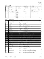
Information List
No.
Information
Type of
Informa-
tion
Comments
009.0100 Failure Modul
IntSP
Failure EN100 Modul
009.0101 Fail Ch1
IntSP
Failure EN100 Link Channel 1 (Ch1)
009.0102 Fail Ch2
IntSP
Failure EN100 Link Channel 2 (Ch2)
Functional Scope
The devices 7UT6x contain a series of protective and additional functions. The scope of hardware and firm-
ware is matched to these functions. Additionally, the control functions can be in accordance with the system
requirements. In addition, individual functions may be enabled or disabled during configuration, or interaction
between functions may be adjusted. Functions not to be used in the actual 7UT6x device can thus be masked
out.
Example for the configuration of the scope of functions:
7UT6x devices are intended to be used for busbars and transformers. Overload protection should only be
applied on transformers. If the device is used for busbars this function is set to
Disabled
, for the trans-
formers this function is set to
Enabled
.
The available protection and additional functions can be configured as
Enabled
or
Disabled
. For various
functions, a choice may be presented between several options which are explained below. Functions config-
ured as
Disabled
are not processed by the 7UT6x. There are no indications, and associated settings (func-
tions, limit values) are not displayed during detailed settings.
Setting Notes
Determination of the Functional Scope
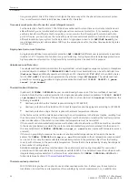
Configuration settings can be entered using a PC and the software program DIGSI and transferred via the front
serial port or the rear service interface. The operation via DIGSI is explained in the
In order to change configuration parameter, entering of password no. 7 (for parameter set) is required.
Without the password, the settings may be read, but may not be modified and transmitted to the device.
Function scope and, if necessary, the available options are set in the Functional Scope dialogue box to match
plant requirements.
2.1.2
2.1.2.1
2.1.2.2
2.1.2.3
2.1.3
2.1.3.1
Functions
2.1 General
30
SIPROTEC 4, 7UT6x, Manual
C53000-G1176-C230-5, Edition 09.2016
Содержание SIPROTEC 4 7UT6 Series
Страница 394: ...394 SIPROTEC 4 7UT6x Manual C53000 G1176 C230 5 Edition 09 2016 ...
Страница 482: ...482 SIPROTEC 4 7UT6x Manual C53000 G1176 C230 5 Edition 09 2016 ...
Страница 504: ...504 SIPROTEC 4 7UT6x Manual C53000 G1176 C230 5 Edition 09 2016 ...
Страница 522: ...522 SIPROTEC 4 7UT6x Manual C53000 G1176 C230 5 Edition 09 2016 ...
Страница 528: ...528 SIPROTEC 4 7UT6x Manual C53000 G1176 C230 5 Edition 09 2016 ...
Страница 538: ...538 SIPROTEC 4 7UT6x Manual C53000 G1176 C230 5 Edition 09 2016 ...
Страница 664: ...664 SIPROTEC 4 7UT6x Manual C53000 G1176 C230 5 Edition 09 2016 ...
Страница 666: ...666 SIPROTEC 4 7UT6x Manual C53000 G1176 C230 5 Edition 09 2016 ...
Страница 683: ...Z Zero sequence currents 109 Index SIPROTEC 4 7UT6x Manual 683 C53000 G1176 C230 5 Edition 09 2016 ...
Страница 684: ...684 SIPROTEC 4 7UT6x Manual C53000 G1176 C230 5 Edition 09 2016 ...


