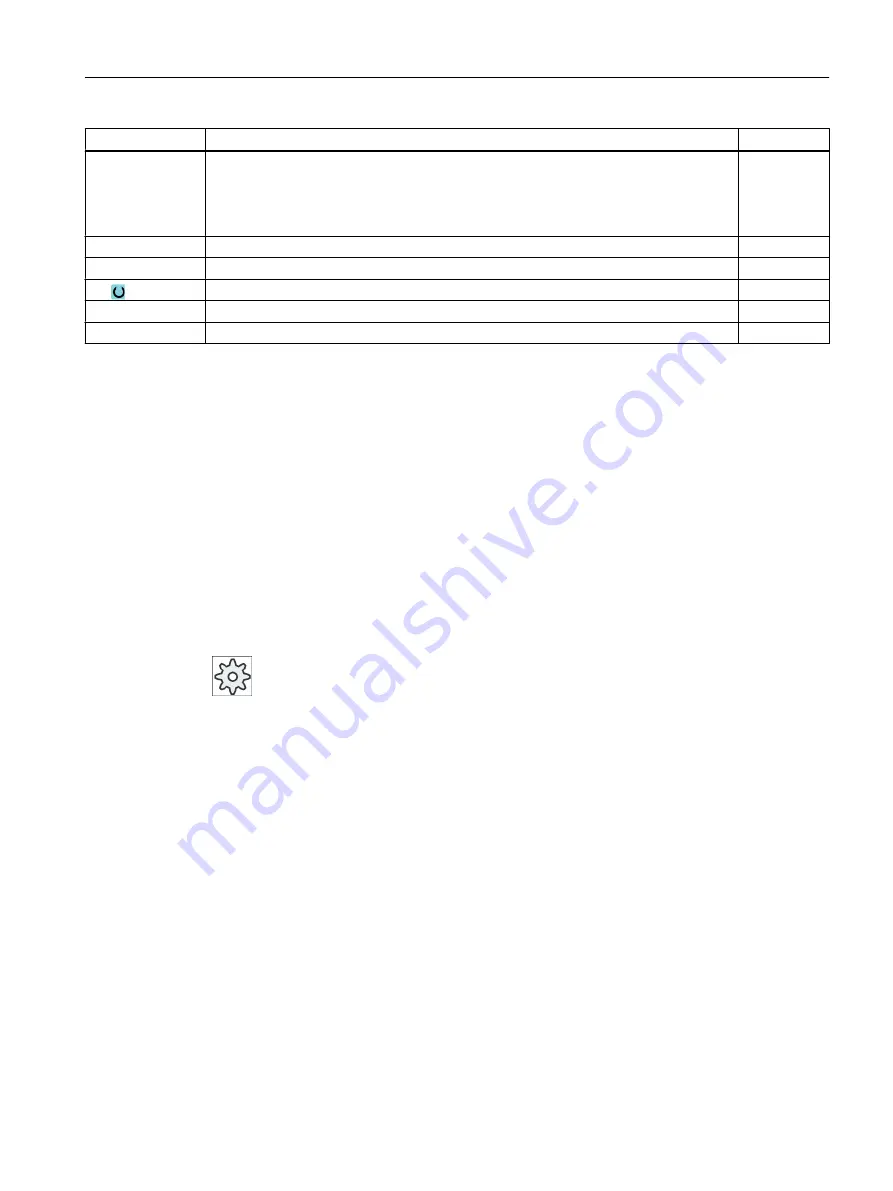
Parameter
Description
Unit
X0
Y0
Z0
The positions refer to the reference point:
Reference point X – (for single position only)
Reference point Y – (for single position only)
Reference point Z
mm
mm
mm
L
Elongated hole length
mm
α0
Angle of rotation
Degrees
Z1
Elongated hole depth (abs) or depth in relation to Z0 (inc)
mm
DZ
Maximum depth infeed
mm
FZ
Depth infeed rate
*
* Unit of feedrate as programmed before the cycle call
10.2.11
Thread milling (CYCLE70)
Function
Using a thread cutter, internal or external threads can be machined with the same pitch.
Threads can be machined as right-hand or left-hand threads and from top to bottom or vice
versa.
For metric threads (thread pitch P in mm/rev), the cycle assigns a value (calculated on the
basis of the thread pitch) to the thread depth H1 parameter. You can change this value. The
default selection must be activated via a machine data code.
Machine manufacturer
Please refer to the machine manufacturer's specifications.
The entered feedrate acts on the workpiece contour, i.e. it refers to the thread diameter.
However the feedrate of the cutter center point is displayed. That is why a smaller value is
displayed for internal threads and a larger value is displayed for external threads than was
entered.
Approach/retraction when milling internal threads
1. Positioning on retraction plane with rapid traverse.
2. Approach of starting point of the approach circle in the current plane with rapid traverse.
3. Infeed to a starting point in the tool axis calculated internally in the controller with rapid
traverse.
4. Approach motion to thread diameter on an approach circle calculated internally in the
controller with the programmed feedrate, taking into account the finishing allowance and
maximum plane infeed.
Programming technological functions (cycles)
10.2 Milling
Milling
Operating Manual, 08/2018, 6FC5398-7CP41-0BA0
471
Содержание SINUMERIK 828D Turning
Страница 68: ...Introduction 2 4 User interface Milling 68 Operating Manual 08 2018 6FC5398 7CP41 0BA0 ...
Страница 162: ...Setting up the machine 4 12 MDA Milling 162 Operating Manual 08 2018 6FC5398 7CP41 0BA0 ...
Страница 270: ...Machining the workpiece 6 17 Setting for automatic mode Milling 270 Operating Manual 08 2018 6FC5398 7CP41 0BA0 ...
Страница 278: ...Swivel combination 45 90 Simulating machining 7 1 Overview Milling 278 Operating Manual 08 2018 6FC5398 7CP41 0BA0 ...
Страница 294: ...Simulating machining 7 9 Displaying simulation alarms Milling 294 Operating Manual 08 2018 6FC5398 7CP41 0BA0 ...
Страница 316: ...Generating a G code program 8 10 Measuring cycle support Milling 316 Operating Manual 08 2018 6FC5398 7CP41 0BA0 ...
Страница 684: ...Collision avoidance 12 2 Set collision avoidance Milling 684 Operating Manual 08 2018 6FC5398 7CP41 0BA0 ...
Страница 746: ...Tool management 13 16 Working with Multitool Milling 746 Operating Manual 08 2018 6FC5398 7CP41 0BA0 ...
Страница 830: ...Alarm error and system messages 15 9 Remote diagnostics Milling 830 Operating Manual 08 2018 6FC5398 7CP41 0BA0 ...
Страница 846: ... Working with Manual Machine 16 7 More complex machining Milling 846 Operating Manual 08 2018 6FC5398 7CP41 0BA0 ...
Страница 870: ...HT 8 840D sl only 18 5 Calibrating the touch panel Milling 870 Operating Manual 08 2018 6FC5398 7CP41 0BA0 ...
Страница 890: ...Easy Message 828D only 20 7 Making settings for Easy Message Milling 890 Operating Manual 08 2018 6FC5398 7CP41 0BA0 ...
Страница 924: ...Edit PLC user program 828D only 23 8 Searching for operands Milling 924 Operating Manual 08 2018 6FC5398 7CP41 0BA0 ...
Страница 925: ...Appendix A A 1 840D sl 828D documentation overview Milling Operating Manual 08 2018 6FC5398 7CP41 0BA0 925 ...


