


For G17, reference points in the plane are called X0 Y0, for G18 they are called Z0 X0 - and
for G19, they are called Y0 Z0. The depth specification in the tool axis for G17 is called Z1, for
G18, Y1 and for G19, X1.
If the entry field remains empty, the parameters, the help screens and the broken-line graphics
are displayed in the default plane (can be set via machine data):
● Turning: G18 (ZX)
● Milling: G17 (XY)
The plane is transferred to the cycles as new parameter. The plane is output in the cycle, i.e.
the cycle runs in the entered plane. It is also possible to leave the plane fields empty and thus
create a plane-independent program.
The entered plane only applies for this cycle (not modal)! At the end of the cycle, the plane
from the main program applies again. In this way, a new cycle can be inserted in a program
without having to change the plane for the remaining program.
8.4.3
Programming a tool (T)
Calling a tool
1.
You are in the part program.
2.
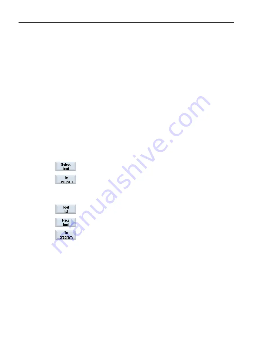
Press the "Select tool” softkey.
The "Tool selection" window is opened.
3.
Position the cursor on the desired tool and press the "To program" softkey.
The selected tool is loaded into the G code editor. Text such as the fol‐
lowing is displayed at the current cursor position in the G code editor:
T="ROUGHINGTOOL100"
- OR -
4.
Press the "Tool list" and "New tool" softkeys.
5.
Then select the required tool using the softkeys on the vertical softkey
bar, parameterize it and then press the softkey "To program".
The selected tool is loaded into the G code editor.
6.
Then program the tool change (M6), the spindle direction (M3/M4), the
spindle speed (S...), the feedrate (F), the feedrate type (G94, G95,...), the
coolant (M7/M8) and, if required, further tool-specific functions.
Generating a G code program
8.4 Fundamentals
Milling
302
Operating Manual, 08/2018, 6FC5398-7CP41-0BA0
Содержание SINUMERIK 828D Turning
Страница 68: ...Introduction 2 4 User interface Milling 68 Operating Manual 08 2018 6FC5398 7CP41 0BA0 ...
Страница 162: ...Setting up the machine 4 12 MDA Milling 162 Operating Manual 08 2018 6FC5398 7CP41 0BA0 ...
Страница 270: ...Machining the workpiece 6 17 Setting for automatic mode Milling 270 Operating Manual 08 2018 6FC5398 7CP41 0BA0 ...
Страница 278: ...Swivel combination 45 90 Simulating machining 7 1 Overview Milling 278 Operating Manual 08 2018 6FC5398 7CP41 0BA0 ...
Страница 294: ...Simulating machining 7 9 Displaying simulation alarms Milling 294 Operating Manual 08 2018 6FC5398 7CP41 0BA0 ...
Страница 316: ...Generating a G code program 8 10 Measuring cycle support Milling 316 Operating Manual 08 2018 6FC5398 7CP41 0BA0 ...
Страница 684: ...Collision avoidance 12 2 Set collision avoidance Milling 684 Operating Manual 08 2018 6FC5398 7CP41 0BA0 ...
Страница 746: ...Tool management 13 16 Working with Multitool Milling 746 Operating Manual 08 2018 6FC5398 7CP41 0BA0 ...
Страница 830: ...Alarm error and system messages 15 9 Remote diagnostics Milling 830 Operating Manual 08 2018 6FC5398 7CP41 0BA0 ...
Страница 846: ... Working with Manual Machine 16 7 More complex machining Milling 846 Operating Manual 08 2018 6FC5398 7CP41 0BA0 ...
Страница 870: ...HT 8 840D sl only 18 5 Calibrating the touch panel Milling 870 Operating Manual 08 2018 6FC5398 7CP41 0BA0 ...
Страница 890: ...Easy Message 828D only 20 7 Making settings for Easy Message Milling 890 Operating Manual 08 2018 6FC5398 7CP41 0BA0 ...
Страница 924: ...Edit PLC user program 828D only 23 8 Searching for operands Milling 924 Operating Manual 08 2018 6FC5398 7CP41 0BA0 ...
Страница 925: ...Appendix A A 1 840D sl 828D documentation overview Milling Operating Manual 08 2018 6FC5398 7CP41 0BA0 925 ...


