


Setting Up
SINUMERIK 801
5
-15
Start-Up
5]
no.): 0 ... 5
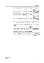
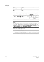
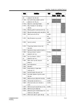
31060 DRIVE_AX_
RATIO_
NUMERA[0
,
1 ...
5]
- Spindle
Numerator
[i]
Numerator
load gearbox
(control
parameter set
no.): 0 ... 5
Notice
A maxium of 5 spindle gear stages can be provided. Assigning the same
parameters to the index [0] and [1] makes gear changes (i=1 ... 5) active only
by setting corresponding interface signals via PLC application.
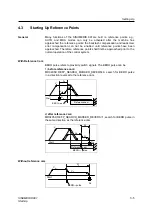
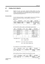
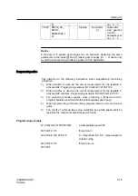
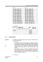
Programming notice
Pay attention to the following instructions when programming machining
programs:
1) When mm/Min is used as the unit of measurement for the feedrate F,
activate G94; Programming example: N10 G94 G01 Z100 F100
2) When mm/Rev is used as the unit of measurement for the feedrate F,
activate G95; mm/Rev. Programming example: N10 G95 G01 Z100 F1
3) For contactor-controlled spindle, when producing a thread with G33,
program spindle speed S within the actual spindle speed range;
4)
When programming a thread cutting, program thread run-in and run-out
paths;
5) The result of a thread lead value multiplied by spindle speed shall be
less than the maximum setpoint speed of Z axis.
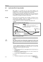
Programming example
N10 G91 G94 F100 S350 M4
;
actual spindle speed 350
N20 G01 Z-0.5
;
thread run-in
N30 G33 Z-100 K2 SF=0
;
K - thread lead; SF
;
SF – Infeed angle for
thread cutting
N40 G01 Z-0.5
;
thread run-out
N50 X50
Содержание Sinumerik 801
Страница 1: ...Start Up 11 2005 Edition sinumerik SIEMENS SINUMERIK 801 ...
Страница 6: ......
Страница 8: ......
Страница 16: ......
Страница 78: ......
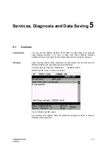
Страница 81: ...Services Diagnosis and Data Saving SINUMERIK 801 5 3 Start Up Fig 5 4 ...
Страница 105: ...A5E00702069 ...