


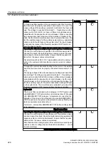


Activity
Available
/completed
Depending on the drive transformer version (dry or oil filled), inte‐
grate the transformer protection and monitoring devices in the alarm
and shutdown train of the drive. A range of digital inputs are available
for this purpose on the customer terminal strip.
Options L80 to L82
The PTC thermistor sensors (type A PTC resistors) must be connec‐
ted to the thermistor motor protection unit ‑F at terminals T1 and T2
for alarm/shutdown purposes.
Options L91; L93, 94, 95, 96
The resistance thermometers must be connected to evaluation unit
‑A1 to evaluate the PT100. The two-wire or three-wire system can be
used here to connect the PT100 sensors. The sensors are divided
into two groups. This must be taken into account when the evaluation
is performed (factory setting).
To check the correct wiring and macro interconnection, first select
limits below the ambient temperature and check the messages.
After checking the correct wiring and macro interconnection, set the
limit values for alarm and shutdown to match the component moni‐
tored.
Differential pressure monitoring
Check the entry for parameter p0263. The setting
must not exceed 3 seconds.
1. In the infeed, select "Test operation cooling" (infeed p6650).
2. Switch on test operation via infeed p6651.
3. In the cooling system, close the main valve for the cooling water
feed to the drive. The drive must switch off with the following fault:
"F49158 cooling system: Differential pressure has fallen below
the fault threshold".
4. Reopen the valve.
5. Acknowledge the fault and switch test operation off again.
( P6651 = 0, P6650 = 0 )
Connecting Sensor Modules
Option K50
If a function for detecting the actual speed value is provided to im‐
prove speed accuracy, connect the motor rotary pulse encoder to the
SMC30 ( A... ).
Option L32
If, for process-related reasons, the drive needs to be restarted after
power failures of > 100 ms, connect the synchronization voltage of
the line upstream of the medium-voltage circuit-breaker to the VSM
10. To do so, install voltage transformers at the medium-voltage lev‐
el, which supply 3-phase 100 V AC as the synchronization voltage.
Connect the voltage transformers on the drive side to terminals.
Checklists and forms
C.2 Checklist for electrical installation
SINAMICS GM150 6SL3835-2LN44-2AA0
Operating Instructions Rev.201910281250 MUSTER
227
Содержание Sinamics GM150 6SL3835-2LN44-2AA0
Страница 2: ...28 10 2019 12 50 V32 00 ...
Страница 14: ...Table of contents SINAMICS GM150 6SL3835 2LN44 2AA0 14 Operating Instructions Rev 201910281250 MUSTER ...
Страница 216: ...Spare parts SINAMICS GM150 6SL3835 2LN44 2AA0 216 Operating Instructions Rev 201910281250 MUSTER ...
Страница 220: ...Service Support SINAMICS GM150 6SL3835 2LN44 2AA0 220 Operating Instructions Rev 201910281250 MUSTER ...
Страница 232: ...Index SINAMICS GM150 6SL3835 2LN44 2AA0 232 Operating Instructions Rev 201910281250 MUSTER ...
Страница 233: ......
Страница 236: ......
Страница 238: ......


