S5-95U, Second Serial Interface
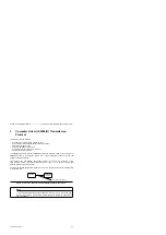
Computer Link with 3964(R) Transmission Protocol
3.2
Data Traffic via Computer Link
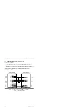
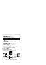
Figure 3-5 describes the principle of operation of the computer link in a schematic diagram.
Figure 3-5 Functional Model of a Computer Link
Error messages
Error messages
S5-95U
Coordination byte
Send (KBS)
(in the flag or data area)
Sending
permitted
Send mailbox (in the
flag or data area)
Number of net data *
Byte 1
Byte 2
Byte 3
.
.
.
.
Byte 1026
1 to 1024 bytes
of net data
a a a a a
a a a a a
a a a a a
a a a a a
a a a a a
Internal
output buffer
(1024 bytes)
Receiving
permitted
Coordination byte
Receive (KBE)
(in the flag or data area)
a a a a
a a a a
a a a a
a a a a
a a a a
Receive mailbox (in the flag
or data area)
Number of net data *
Byte 1
Byte 2
Byte 3
.
.
.
.
Byte 1026
1 to 1024 bytes
of net data
Internal
input buffer
(1024 bytes)
Communication partners
SIEMENS device with computer link capability
*
Byte 1
ˆ
-
most significant half; Byte 2
ˆ
-
least significant half
Data can be transmitted in both directions:
•
Send direction
Data included in the send mailbox (SF) (e.g. contents of a DBx) are buffered in an output buffer
and then sent to the other communications partner.
•
Receive direction
The communication partner sends data to interface SI2 of S5-95U. The data is buffered in the
input buffer and written into the receive mailbox (EF) on initiation by the PLC program.
The send and receive mailboxes may be located in the same data block or flag area.
EWA 4NEB 812 6095-02
3-5

