S5-95U, Second Serial Interface
Technical Data, Scan On-Load Times
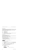
2. Compute time for a bus cycle
The time for one bus cycle (cycle time T
C
in ms) can be calculated by means of the following
equation:
T
C
=
(20 +
L
m
· 1.8
+
L
s
· 1.8
+
t
Q
) · n
T
C
=
Bus cycle time for n nodes for identical frame lengths (m) master slave
for identical frame lengths (s) slave master
L
M
=
Number of bytes in the case of the master
L
s
=
Number of bytes in the case of the slave
t
Q
=
20 ms, for internode communication only (i.e. slave sends data to other slave)
n
=
Number of slaves (n=1 is always valid in the case of point-to-point link)
For S5-95U as point-to-point master, the following equation is valid in the range
100 ms T
C
280 ms.
Example:
S5-95U is SINEC L1 slave
Number of bytes in the case of the master
=
64 bytes
Number of bytes in the case of the slave
=
64 bytes
Number of slaves
=
15
T
C
=(20+64 bytes·1.8+64 bytes·1.8)·15
T
C
=3756 ms
--------------------
18.5 ms
3756 ms
PLC load time
Bus cycle time
=
= 0.005
--------
The PLC scan time increases by 0.5% on account of SINEC L1 communication at the
SI2 interface provided the PLC scan cycle is just as long as the bus cycle. For short
PLC scan cycles, the load resulting from SINEC L1 communication is not evenly
distributed.
In the case of computer link/ASCII driver:
When sending, the first load occurs within 100 ms, i.e. the send request is recognized by the driver
in the operating system of the PLC (32 bytes are copied by the send mailbox into the internal output
buffer).
When receiving, the first load occurs when the KBE bit
”
Receiving permitted
”
is set and receive
data are available.
Further loads occur both during sending and receiving at intervals of approx. 10 ms.
The number of loads depends on the data quantity:
•
Worst case für 1 ... 32 bytes
=
1 ms
•
Worst case für 1024 bytes
=
32·1 ms
EWA 4NEB 812 6095-02
E-3

