Hardware Installation
CP 523
3.4
Terminal Diagrams
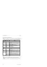
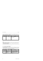
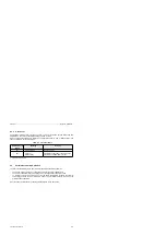
This section contains typical terminal diagrams for connecting the following:
•
A printer (PT 88)
•
A point-to-point connection (data terminal equipment DTE)
-
CP 523 to CP 523
-
CP 523 to CPU 944
•
Modem link (data communications equipment DCE)
3.4.1
Terminal Diagrams for Print Mode
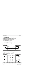
The CP 523 assumes a printer with an RS-232-C (V.24) or TTY interface as the peripheral device.
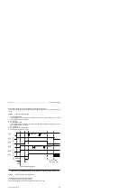
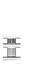
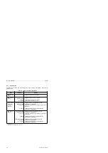
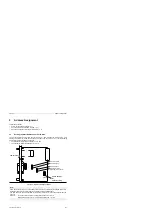
CP 523 (passive TTY) to PT 88 (active TTY) without BUSY signal
Figure 3-6. Pin Assignments for CP 523 (Passive TTY) to PT 88 (Active TTY) without BUSY Signal
PT 88
Shield
(24)
(1) Shield
Shield
(25)
TTY OUT - (12)
(9) TTY IN+
TTY OUT+ (10)
(10) TTY IN –
20 mA
CP 523
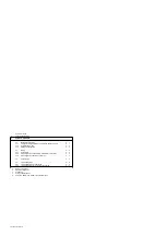
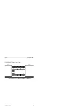
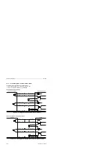
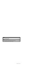
CP 523 (passive TTY) to PT 88 (active TTY) with BUSY signal
Figure 3-7. Pin Assignments for CP 523 (Passive TTY) to PT 88 (Active TTY) with BUSY Signal
TTY IN+
(6)
(21) TTY OUT -
Shield
(24)
(1) Shield
Shield
(25)
TTY OUT+ (10)
(10) TTY IN -
TTY OUT - (12)
(9) TTY IN+
TTY IN -
(8)
(18) TTY
OUT+
20 mA
CP 523
PT 88
20 mA
Printer setting: Printer not ready to receive = no current
3-8
EWA 4NEB 811 6044-02a

