Installation and Startup
5-6
PROFIBUS Optical Bus Terminal (OBT)
C79000-G8976-C122-03
Connecting the Optical Cables
A
B
C
D
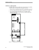
Figure 5-4
View of the Module from Below with the Optical Channels CH2 and CH3
A = CH2, optical receiver
B = CH2, optical sender
C = CH3, optical receiver
D = CH3, optical sender
Connect the individual PROFIBUS OBTs using a duplex FO cable, fitted with
two pairs of simplex connectors.
Make sure that in each case an optical input is connected to an optical output
(crossover).
Make sure that there is reliable strain relief for the FO cable and do not bend
the cable beyond the minimum bending radius.
Close unused FO sockets with the plastic plugs provided. Extraneous light,
particularly when it is extremely bright can cause disturbances on the
PROFIBUS network.
Remember the minimum and maximum length of the FO cable and the
permitted fiber types specified in Table 1 and in the technical specifications.
You should also make sure that no dust can enter the optical components. Dust
in optical components can make them unusable.
The fibers of the cable must be flush with the front surface of the connector.
Содержание SIMATIC NET PROFIBUS OBT
Страница 4: ...Contents ii PROFIBUS Optical Bus Terminal OBT C79000 G8976 C122 03 Contents ...
Страница 8: ...The SIMATIC NET PROFIBUS OBT Product 2 2 PROFIBUS Optical Bus Terminal OBT C79000 G8976 C122 03 ...
Страница 16: ...Network Topology 4 4 PROFIBUS Optical Bus Terminal OBT C79000 G8976 C122 03 ...
Страница 24: ...Installation and Startup 5 8 PROFIBUS Optical Bus Terminal OBT C79000 G8976 C122 03 ...
Страница 26: ...Troubleshooting 6 2 PROFIBUS Optical Bus Terminal OBT C79000 G8976 C122 03 ...
Страница 30: ...Technical Specifications 7 4 PROFIBUS Optical Bus Terminal OBT C79000 G8976 C122 03 ...
Страница 34: ...References 9 2 PROFIBUS Optical Bus Terminal OBT C79000 G8976 C122 03 ...
Страница 36: ...Abbreviations 10 2 PROFIBUS Optical Bus Terminal OBT C79000 G8976 C122 03 ...


