


Cold room gate drive ATD400K
A2B00101049-01, 08/2012
31
Note
The motor temperature must not be below 0°C during the learn run, as otherwise the weight of the gate will be incorrectly
determined, and the closing and nudge speeds may lie in impermissible ranges.
Procedure
1.
Push the cold room gate into the CLOSED position.
2.
Open housing lid.
3.
Plug in the X7 motor plug.
Note
The X6 control inputs plug is not plugged in during commissioning in order to prevent uncontrolled movements.
4.
Connect the power supply to the 230 VAC mains supply. The on-site fuse must not exceed 10 A.
5.
Press and hold down the learn run button (S401).
6.
Connect the power supply output to X3.
7.
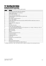
The learn run starts automatically, and the learn run button can be released. The 7-segment display (H401) shows "H.".
During the learn run, the door is opened about 10cm, and closed once or twice at creep speed. The friction of the cold
room gate system is then determined by opening and closing the gate once through a range of 25cm at creep speed.
The cold room gate then opens and closes through its complete range of movement at reduced speed. After the gate has
opened about 10 cm, it passes through a short acceleration ramp to determine the weight of the gate. In the CLOSED
position, the profile parameters and the determined gate width are saved. The decimal point in the 7-segment display
(H401) flashes during the save process. The 7-segment display (H401) shows "u" when saving has finished.
8.
The cold room gate can now be opened with the OPEN button S402. The 7-segment display (H401) shows "o" while the
door is opening.
9.
Switch off the controller by pulling out the power plug or the X3 plug.
10.
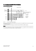
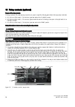
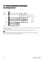
Connect the control signals to the X6 connector as shown in the terminal circuit diagram (see Terminal circuit diagram of
11.
Connect the light barrier or gate interlocking to X6 (see Overview of controls (Page 28) or text on cover). If input 1 (light
barrier or gate interlocking) is not used, X6 must be wired to X4 as indicated by the lines in the layout diagram.
12.
Plug in terminal connectors X6 and X4.
13.
Switch on the controller (plug in the power plug or the X3 plug). The four LEDs alongside the plug connector X6 indicate
which control signal is currently active. Input 1 (light barrier or gate interlocking) is active if the LED does not light up.
14.
If the control signal CLOSE is present, the cold room gate moves into the CLOSED position at initial speed. If an OPEN
control signal is present, the cold room gate moves into the OPEN position at initial speed.
15.
Once the controller has detected the gate OPEN and CLOSED end positions, the subsequent opening and closing
movements proceed once again at normal speed.
16.
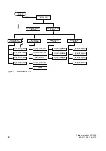
The travel values can be individually matched to the cold room gate for specific applications using the integrated terminal
module or the Service Tool (optional). Parameters can also be changed with the aid of the Sidoor User Software
(optional, part of the Sidoor Software Kit). Simple settings can also be made with the three buttons and the 7-segment
display on the basic unit via the Electrical adjustment with the minimal editor (Page 35).


