5
1.
Erect mast and base.
Erect five inch mast, with junction box base on the track side. Mounting hole for
front and back flashing lights will be on the field side of mast. Place a level on the mast and plumb to
vertical using large shim washers or leveling nuts on the foundation bolts.
2.
Mount support clamp on mast.
Support clamp 070786-5X mounts on the mast with casting facing 45°
from the field side toward track. The top of casting should be approximately 51” above the top of foun-
dation (page 16, item 5). (Actual height may vary depending on local conditions.)
3.
Prepare mechanism.
Thread 90° flex conduit coupling into the back of the gate cabinet and insert the 4
square head machine bolts into the slots on the back of cabinet (page 18, items 72 & 76).
4.
Clamp mechanism in place.
Lift mechanism (see page 7) and set on top of the support clamp. Clamp
to mast with clamps, nuts and washers provided (page 18, items 75, 77, 78 & 79).
5.
Install arm supports.
Apply a small amount of Safetran No-oxide Grease PN 032401-X on the main
shaft threads. Mount gate arm supports with bolted on hubs over the keys on the main shaft ends.
Install main shaft nuts and washers (page 18, items 36 & 37) but
do not fully tighten
until after install-
ing the conversion bracket.
6.
Install arm coupling or conversion bracket.
Bolt to the arm support castings and then
fully tighten
the main shaft nuts.
7.
Install flexible conduit.
Thread coupling into base and install conduit to base and rear of cabinet. See
diagram page 6 (page 18, items 73 & 74).
8.
Mount flashing lights, bell and signs.
The flashing light units have been factory wired but control
wires from the lights junction box to the junction box base must be field installed.
Align the flashing
light units before placing the crossing in service
. Bell, when used, is mounted on top of the mast
with the gong facing the roadway. A spare contact is provided on the gate controller to cut off bell when
the gate arm is down (see wiring page 3). Mount the required signs.
9.
Connect power to mechanism.
See page 4 for recommended battery and wire requirements and
connect per wiring diagram page 3. Seal conduit opening per AREMA Signal Manual Part 2.4.25.
10.
Install counterweight stud plates.
Ensure the roller spacers are over the studs and in the arm support
slot before mounting clamp bar and locking piece. See page 22, items 8,4,11,12 & 13.
11.
Install counterweights and gate arm as follows:
If required, the back clamps can be loosened and
the mechanism rotated parallel to the roadway for arm installation.
a.
Install counterweights.
With the arm supports in “arm up position”, install up to 6 counter
weights (12 short type) at this time. Total number required per tables on pages 10 & 24.
Position the counterweights with the large corner radius to the field or up position and
locate maximum to the field or up position (see diagram page 11).
Short arm installations may require extending counterweights as shown on page 24.
b.
Raise counterweights.
Raise to horizontal using the maintenance switch per
pages 13 and 14.
I
NSTALLATION
S
TEPS
(Continued next page)
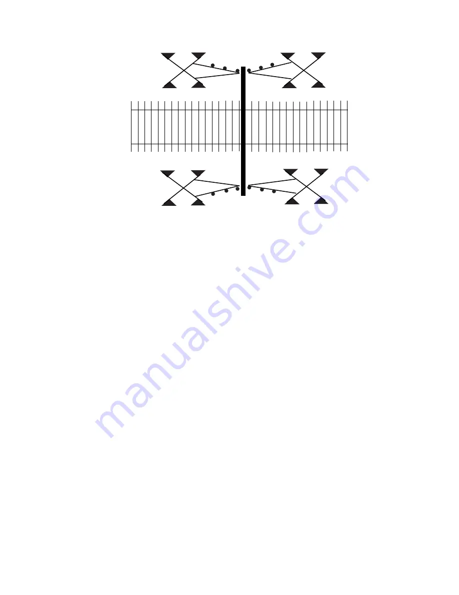
EXIT Gate
Front Lights
Back Lights
Entrance Gate
Front Lights
Back Lights
EXIT Gate
Track Side
Entrance Gate
Road Side
Field Side
Содержание S-40EXIT
Страница 5: ...3 ...
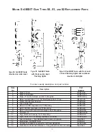
Страница 20: ...18 S 40EXIT Gate Exploded View ...
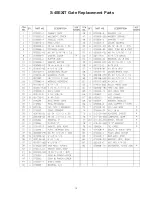
Страница 21: ...19 S 40EXIT Gate Replacement Parts ...
Страница 27: ......


