Technical Instructions
RWD68U Universal Controller
Document Number 155-738
January 14, 2005
Mechanical Design
Protective Housing
ARG62.21
•
This UL-approved plastic housing protects the controller when mounted outside a
control panel, such as on ducts, walls and in mechanical rooms. This housing
also prevents inadvertent contact with voltage supplying parts such as the
connecting terminals.
•
The RWD68U clips into the housing.
•
The cable entries are located at the top and the bottom of the ARG62.21
housing.
•
The front has an opening for the LCD display and the programming buttons.
Terminals
Plug-in screw terminals
Operating and Display
Elements
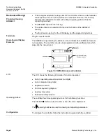
The RWD68U is operated by the buttons on the controller front.
Additional tools are
not necessary. The controller can also be programmed via the software tool, which
plugs into the nine-pin port.
TH0762R1
LCD Display
Software Tool
Nine Pin Port
Program and Display
Function Buttons
Figure 19. RWD68U Universal Controller.
LCD
The LCD shows the following information for normal operation:
•
Current operating values (maximum four digits)
•
Current setpoints (day/night)
•
Application number
•
Control sequencing diagram
•
Auxiliary input value
•
Selected auxiliary function
Operating Buttons
The controller has three operating buttons for the following functions:
The SELECT
●
button is used to enter or save the value adjustment.
The operating buttons are used for viewing and adjusting parameters.
Configuration
To configure the controller, follow the instructions supplied with the controller.
Page 8
Siemens Building Technologies, Inc.


