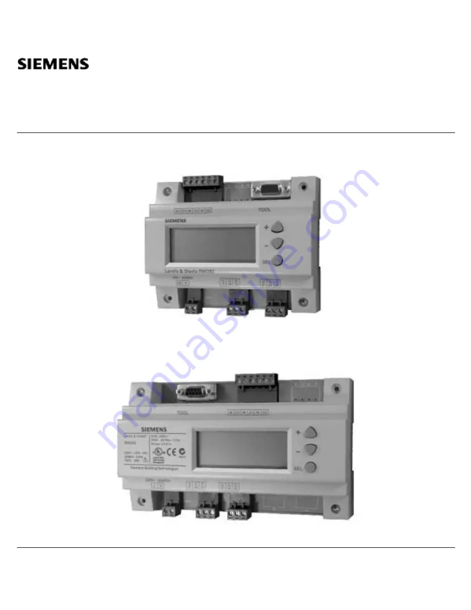
Siemens Building Technologies
O3341(RWD32) V14.doc
O3341A031En2
8-Jun-01
Page 1
Version 2
Installation and Commissioning Guide
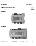
RWD82
RWD32
RWD82RWD32
Страница 1: ...Siemens Building Technologies O3341 RWD32 V14 doc O3341A031En2 8 Jun 01 Page 1 O3341A031En2 Version 2 Installation and Commissioning Guide RWD82 RWD32 RWD82 RWD32 ...
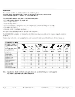
Страница 2: ...ail mounting in a switchboard or screw mounting with protective enclosure Desired output configuration and auxiliary function must be entered for initial setup Refer to Service PS mode sequence Application No Summary H Heating C Cooling R Reverse Acting D Direct Acting The 1st digit Main Control Loop The 2nd digit Auxiliary Control Loop Main Loop 1x H H or R R depend 2x H H or R R independ 3x H or...
Страница 3: ...miter mode being chosen or activated K Kelvin REM Remote setpoint mode being chosen or activated Percentage scale e g RH COMP Setpoint compensation mode being chosen or activated No unit e g pressure air quality and air volume flow CAS Cascade mode being chosen or activated Sec Second MaxPrior Maximum priority mode being chosen or activated Q1 Digital output 1 is on is off SP h Setpoint on the hea...
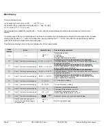
Страница 4: ...on band for direct acting Active input 0 05 7300 MIN Minimum Limiter 100 7980 TN h Integral action time for heating 0 4096 sec WIN Winter changeover point 100 8000 TN c Integral action time for cooling 0 4096 sec SUM Summer changeover point 100 8000 TN r Integral action time for reverse acting 0 4096 sec TN d Integral action time for direct acting 0 4096 sec PS 2 Unit X1 X2 sensor type and sensing...
Страница 5: ...IN As X2 WIN Q1 is reverse acting x SUM As X2 SUM Q1 is direct acting x T Time elapsed to allow next winter summer changeover Q1 only x x There are no PS3 auxiliary function parameters for applications 8 and 9 Operating Modes The controller has three operating buttons for the following functions SELECT The SELECT button is used to enter or save the value adjustment The operating buttons are used f...
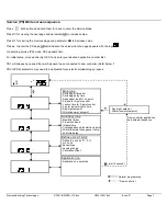
Страница 6: ...oling direct or reverse day acting setpoint depending on application Push button to enter next page Q2 SP c 21 0 C Setpoint page setting value displayed and is adjustable Second stage heating or cooling direct or reverse day acting setpoint depending on application Push button to enter next page Q1 SP h 15 0 C Setpoint page setting value displayed and is adjustable First stage heating or cooling d...
Страница 7: ...int Winter summer setpoint Main loop C Q1 Q2 X1 wait 2 second New controller application and setpoint sequence New controller Normal programming Service PS Mode screen sequence Press both buttons and hold them for 5 sec to enter the Service Mode Press for viewing the next page and parameter OR to increase value Press for viewing the previous page and parameter OR to decrease value Press to enter t...
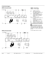
Страница 8: ...lock or switch Q1 Q2 Potential free relay contacts for 3 position or 2 position control in 2 steps Y1 Actuator with 3 position control AC 24 230 V E1 Electrical load 2 position control PC Desktop or notebook computer Note Output relay contacts potential free can be supplied with AC 24 to 230 volts RWD32 Connection Diagram L S1 D1 N B M B M X1 X2 M M X2 X1 M Q12 Q14 L AC 230 V N RWD32 Q11 Y1 Y1 Q22...
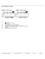
Страница 9: ...21 D1 M X1 M X2 M G Q24 Q22 Q11 Q14 Q12 Tool Tool G G0 AC 24 V supply SELV AC 24 V Power supply L N AC 230 V supply M Ground G0 for signal inputs and universal inputs X1 Signal input main input LS Ni 1000 Pt 1000 and 0 10 Vdc X2 Signal input aux Input LS Ni 1000 Pt 1000 0 10 Vdc and remote setting unit Q Digital output various voltages permissible D1 Digital input Tool communication port with PC 9...
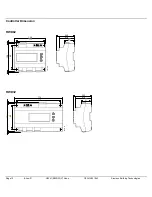
Страница 10: ...Page 10 8 Jun 01 O3341 RWD32 V14 doc O3341A031En2 Siemens Building Technologies Controller Dimension RWD82 130 106 89 111 56 5 47 9 31 3341m01 4 4 RWD32 155 106 89 174 3341m02 56 5 47 9 31 4 4 ...
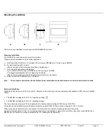
Страница 11: ...the ARG62 21 RWD82 only ARG62 22 Note There must be a minimum of 8mm distance from terminations to panel enclosures in order to avoid electric shock Electrical installation Standard cables can be used for the controller However when mounting in an environment greatly exposed to EMI use only shielded cables The RWD32 is designed for AC 230 V operating voltage The RWD82 is designed for AC 24 V opera...
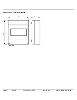
Страница 12: ...Page 12 8 Jun 01 O3341 RWD32 V14 doc O3341A031En2 Siemens Building Technologies Mounting Enclosure Dimensions 150 200 ARG62 21 59 7 ...