background image


Table of Contents

RUGGEDCOM WIN5214

Installation Guide

iv

Chapter 3

Device Management .......................................................................................  

25

3.1  Configuring the Subscriber Unit ...................................................................................................  25

Chapter 4

Technical Specifications ..................................................................................  

27

4.1  Power Consumption .................................................................................................................... 27
4.2  Radio and Modem Specifications .................................................................................................. 27
4.3  Operating Environment ...............................................................................................................  28
4.4  Mechanical Specifications ............................................................................................................ 28
4.5  IDU to ODU Cable Specifications ..................................................................................................  28
4.6  Dimension Drawings ...................................................................................................................  30

Chapter 5

Certification ....................................................................................................  

31

5.1  Approvals ...................................................................................................................................  31

5.1.1  MET Laboratories .............................................................................................................  31
5.1.2  CSA ................................................................................................................................. 32
5.1.3  European Union (EU) .......................................................................................................  33
5.1.4  TÜV Rheinland .................................................................................................................  33
5.1.5  IEEE ................................................................................................................................  33
5.1.6  RoHS ............................................................................................................................... 33
5.2  Environmental Type Tests ............................................................................................................ 34

Содержание RUGGEDCOM WIN5214

Страница 1: ...RUGGEDCOM WIN5214 Installation Guide 10 2018 RC1130 EN 07 Preface Introduction 1 Installing the Subscriber Unit 2 Device Management 3 Technical Specifications 4 Certification 5 ...

Страница 2: ...that you regularly check for product updates For the secure operation of Siemens products and solutions it is necessary to take suitable preventive action e g cell protection concept and integrate each component into a holistic state of the art industrial security concept Third party products that may be in use should also be considered For more information about industrial security visit https ww...

Страница 3: ... Precautions 7 2 4 Installing the Subscriber Unit in Hazardous Locations 9 2 5 Mounting the Subscriber Unit 9 2 5 1 Mounting the Subscriber Unit to a Wall or Tower 10 2 5 2 Mounting the Subscriber Unit to a Pole 12 2 6 Grounding the Subscriber Unit 14 2 7 Connecting Power and Data 14 2 7 1 Connecting the RUGGEDCOM WIN1010 15 2 7 2 Connecting to a RUGGEDCOM RP100 or RP110 16 2 7 3 Assembling the Po...

Страница 4: ...er Consumption 27 4 2 Radio and Modem Specifications 27 4 3 Operating Environment 28 4 4 Mechanical Specifications 28 4 5 IDU to ODU Cable Specifications 28 4 6 Dimension Drawings 30 Chapter 5 Certification 31 5 1 Approvals 31 5 1 1 MET Laboratories 31 5 1 2 CSA 32 5 1 3 European Union EU 33 5 1 4 TÜV Rheinland 33 5 1 5 IEEE 33 5 1 6 RoHS 33 5 2 Environmental Type Tests 34 ...

Страница 5: ...dures should not rely on this manual for comprehensive guidance CONTENTS Alerts Related Documents Training Customer Support Alerts The following types of alerts are used when necessary to highlight important information DANGER DANGER alerts describe imminently hazardous situations that if not avoided will result in death or serious injury WARNING WARNING alerts describe hazardous situations that i...

Страница 6: ...ortation and industrial markets allows Siemens to provide training specific to the customer s application For more information about training services and course availability visit https www siemens com ruggedcom or contact a Siemens Sales representative Customer Support Customer support is available 24 hours 7 days a week for all Siemens customers For technical support or general information cont...

Страница 7: ...ltipoint broadband wireless access applications the subscriber unit provides efficient use of the wireless spectrum supporting a range of user environments The subscriber unit also complies with the IEEE 802 16 2005 standard for the deployment of point to multipoint PMP and point to point PTP network architectures The subscriber unit is a WiMAX Forum IEEE 802 16e Wave 2 MIMO certified subscriber E...

Страница 8: ...y to separate traffic types over the air and guarantee latency minimum bandwidth and jitter according to application needs Power Supply Options When combined with the injector series RUGGEDCOM RP100 or RP110 the subscriber unit offers the industry s leading power supply options with 12 VDC 24 VDC 48 VDC and 88 300 VDC or 85 264 VAC available for a variety of industrial applications Flexibility The...

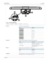
Страница 9: ... 60 20 W LINK LED Indicates when the subscriber unit is connected with a base station State Description Green Solid Subscriber unit is connected to the base station and receiving services Green Blinking Link between the subscriber unit and the base station is down PWR LED Indicates when power is supplied to the subscriber unit State Description Green Power is on Off Power is off ETH PWR Port A cop...

Страница 10: ... or 1 9 in inner diameter before shrinking or self amalgamating tape UV resistant vinyl tape Electrical insulation putty Mounting Hardware Wall Tower Only Four 1 4 1 2 HEX chipboard screws Four 1 4 flat washers Four 1 4 spring washers Section 1 4 Decommissioning and Disposal Proper decomissioning and disposal of this device is important to prevent malicious users from obtaining proprietary informa...

Страница 11: ...t or its outdoor cables Therefore install the lightning protector indoors as close as possible to the point where the cables enter the building The lightning protector can also be installed outdoors as long as the cables that lead indoors are well protected from lightning between the protector and the building entrance WARNING Safety hazard risk of serious personal injury and or damage to equipmen...

Страница 12: ...40 ft must be considered as TNV 1 circuits The installer must make sure the power supply and network ports are designed for full compliance with the standards for TNV 1 telecommunication networks CONTENTS Section 2 1 General Procedure Section 2 2 Unpacking the Subscriber Unit Section 2 3 Site Preparation and Precautions Section 2 4 Installing the Subscriber Unit in Hazardous Locations Section 2 5 ...

Страница 13: ... in the RUGGEDCOM WIN5214 package Item Quantity RUGGEDCOM WIN5214 Subscriber Unit 1 RUGGEDCOM WIN1010 AC Power Injector 1 Radio Frequency RF antenna cables 5 m 16 4 ft long 2 Pole wall tower mounting kit 1 RJ45 PoE Connector Kit 1 When unpacking the subscriber unit do the following 1 Inspect the package for damage before opening it 2 Visually inspect each item in the package for any physical damag...

Страница 14: ...site including potential mounting points for the subscriber unit and antennas as well as the routing options for data power and antenna cables For safety always consult with the local power utility as well It is important to select a site that not only offers maximum coverage but is also safe for installers to work in Safety Precautions When installing the subscriber unit or an antenna make sure t...

Страница 15: ...ambda DPP50 48 Power Supply in conjunction with the unit NOTE For further details of the subscriber unit s compliance with Class I Division 2 Zone 2 standards refer to Section 5 1 Approvals Sample Hazardous Location Label The following is an example of the RUGGEDCOM WIN5214 hazardous location label P N WiN52XX Y ZZZ CPE xxxx xxxx MHz S N XXXXWWYYXX WARNING EXPLOSION HAZARD DO NOT SEPARATE WHILE CI...

Страница 16: ...oints for the subscriber unit and antennas as well as the routing options for data power and antenna cables Recommended Site Requirements It is highly recommended the subscriber unit be mounted with as few obstructions as possible between itself and the base station The subscriber unit should be pointed in the direction of the designated server base station When choosing the ideal location it is a...

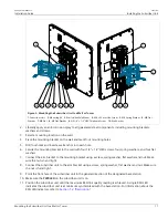
Страница 17: ...l four holes and insert a wall anchor into each hole 6 Secure the mounting bracket to the wall with four 1 4 1 2 HEX screws four spring washers and four flat washers 7 Connect the arm bracket to the mounting bracket using a screw spring washer flat washer and nut Make sure the nut is hand tight 8 Connect the subscriber unit to the arm bracket using a screw spring washer flat washer and nut Make su...

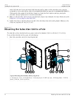
Страница 18: ...nded according to local standards For more information refer to Section 2 6 Grounding the Subscriber Unit 13 Tighten the screws connecting the arm bracket to the subscriber unit and mounting bracket Make sure the screws are torqued to 24 N m 17 7 ft lb Section 2 5 2 Mounting the Subscriber Unit to a Pole The subscriber unit can be attached to any pipe or pole with a diameter of 44 5 to 254 mm 1 75...

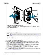
Страница 19: ...ts Make sure the screws are hand tightened 6 Point the front face of the subscriber unit in the general direction of the designated base station 7 Make sure the PWR LED on the subscriber unit is on 8 Position the subscriber unit until the maximum RSSI link quality reading is achieved A single RSSI LED indicates the subscriber unit is at minimum synchronized with the base station For information ab...

Страница 20: ...ce with the local electrical codes Section 2 7 Connecting Power and Data The subscriber unit can be connected to one of the following Power over Ethernet PoE injectors in non hazardous locations RUGGEDCOM WIN1010 included RUGGEDCOM RP100 RUGGEDCOM RP110 CAUTION Crushing hazard risk of damage to cables Route all power supply cables so that people cannot walk on them or place objects on or against t...

Страница 21: ...rushing hazard risk of damage to equipment Route all power supply cables so that people cannot walk on them or place objects on or against them This can pinch or damage the cords 1 Connect an indoor to outdoor CAT 5e cable to the Ethernet port on the injector For information on cable requirements refer to Section 4 5 IDU to ODU Cable Specifications 2 Apply the PoE connector kit to the other end of...

Страница 22: ...lightning protector NOTE The lightning protector must meet the necessary requirements of IEC UL CSA 60950 1 The clamping voltage must also be less than 60 V and the protector must not activate when the voltage is less than 56 V For more information about these requirements contact Siemens Customer Support IMPORTANT Install the lightning protector and the RUGGEDCOM RP100 RP110 as close as possible ...

Страница 23: ... to Section 4 5 IDU to ODU Cable Specifications Standard cable splicing tools including a standard crimp tool To assemble the PoE connector do the following 1 Slide the connector components on to the wire 1 2 Figure 8 Assembling the Connector Components 1 Plug Housing 2 Dust Cover 2 Strip the wire jacket 38 mm 1 5 in from the tip making sure not to cut the foil or drain wire 38 mm 1 5 in 1 2 Figur...

Страница 24: ... 1 Foil 2 Twisted Pair Wires 3 Drain Wire 4 Bend the drain wire back over the jacket 3 1 2 Figure 11 Bending the Drain Wire 1 Foil 2 Drain Wire 3 Twisted Pair Wires 5 Partially untwist each wire pair making sure to retain a half twist at the end Figure 12 Untwisting the Wire Pairs 6 Arrange the wires according to the following pin out description ...

Страница 25: ...ers to hold the wires while pulling the loading bar 1 2 2 1 1 3 4 1 1 2 3 4 5 6 7 8 2 3 4 5 6 7 8 Figure 14 1 Loading Bar 2 Wires 3 Pin 1 4 Pin 8 8 Trim the wires until they are flush with the face of the loading bar 9 Insert the wires and loading bar into the plug body Make sure the cable is pushed to the front of the plug body the spine of the strain relief on the plug body covers the drain wire...

Страница 26: ... 5 In lbs Section 2 7 4 Installing the Hazardous Location Kit An approved Power over Ethernet PoE injector is required when the subscriber unit is installed in a hazardous location The RUGGEDCOM WIN5214 is certified for installation in Class I Division 2 Groups A B C and D hazardous locations when installed using the Class I Division 2 kit P N MKIT0090 The Class I Division 2 kit contains the follo...

Страница 27: ...according to national rules 4 Connect the open ended AC power cable to the power supply unit Section 2 8 Weatherproofing the Subscriber Unit Most outdoor subscriber unit antenna and cable problems are caused by coaxial cable connections loosened by vibration allowing moisture to penetrate the connector interface Siemens strongly recommends weatherproofing all outdoor cable connections to prevent t...

Страница 28: ...shrink or self amalgamating tape to the connector end For information about how to apply these types of seals refer to Section 2 8 2 Applying Cold Shrink Tubing or Section 2 8 3 Applying Self Amalgamating Tape 4 Apply two layers of UV resistant vinyl tape to the cable ends 5 Apply electrical insulation putty around the very end of the cable to form a seal between it and the base station 6 If the s...

Страница 29: ...removed Section 2 8 3 Applying Self Amalgamating Tape To apply self amalgamating or self fusing tape to a cable end do the following IMPORTANT When applying self amalgamating tape make sure to stretch it to 2 3 of its original width to form a tight seal 1 Cut a strip of self amalgamating tape approximately 50 cm 19 7 in long 2 Apply one end of the tape to the cable end and tightly wrap it around t...

Страница 30: ...Chapter 2 Installing the Subscriber Unit RUGGEDCOM WIN5214 Installation Guide 24 Applying Self Amalgamating Tape ...

Страница 31: ... Subscriber Unit Section 3 1 Configuring the Subscriber Unit Once the subscriber unit is installed and connected to the network it must be configured The RUGGEDCOM WIN5214 features a Web based User Interface UI for all configuration management For more information about configuring the subscriber unit refer to the RUGGEDCOM WIN Subscriber Unit User Guide associated with the subscriber unit and the...

Страница 32: ...Chapter 3 Device Management RUGGEDCOM WIN5214 Installation Guide 26 Configuring the Subscriber Unit ...

Страница 33: ...Specifications Section 4 5 IDU to ODU Cable Specifications Section 4 6 Dimension Drawings Section 4 1 Power Consumption Typical Power Consumption 12 W Section 4 2 Radio and Modem Specifications Operating Frequency 1350 to 1525 MHz Wireless Communication Standard IEEE 802 16e 2009 Operating Mode Time Division Duplexing TDD Channel Bandwidths 3 5 MHz 5 MHz 7 MHz 10 MHz Frequency Resolution 250 kHz T...

Страница 34: ...he center of the enclosure b Non condensing Section 4 4 Mechanical Specifications Weight 1 5 kg 3 3 lb Ingress Protection IP67 Enclosure Aluminum Section 4 5 IDU to ODU Cable Specifications IDU to ODU Cable Applications Outdoor installations fixed or portable installations digital distribution frames in transmission stations outdoor installations in harsh environments General Construction Custom m...

Страница 35: ...minum Polyester Foil Overall Foil Design 100 Coverage Overall Drain wire Material Tinned Copper Overall Drain wire Size 24 AWG Overall Drain wire Construction Stranded Inner Jacket Material UV resistant FR PVC Inner Jacket Diameter 6 1 mm 0 24 in Total Number of Wires 8 IDU to ODU Cable Standards Flammability Rating IEC 60332 UL1581 VW 1 Standards IEC 61156 TIA EIA 568 IDU to ODU Cable Performance...

Страница 36: ...electric Strength to Shield 700 V minute Minimum Bend Radius 70 mm 2 8 in Operating Temperature Range 40 to 70 C 40 to 158 F Section 4 6 Dimension Drawings NOTE All dimensions are in millimeters unless otherwise stated 305 0 305 0 11 0 154 0 325 8 183 0 38 7 63 8 53 7 Figure 17 Overall Dimensions ...

Страница 37: ...European Union EU Section 5 1 4 TÜV Rheinland Section 5 1 5 IEEE Section 5 1 6 RoHS Section 5 1 1 MET Laboratories This subscriber unit meets the requirements of the following standards Low Voltage Directive 2006 95 EC Directive 2006 95 EC of the European Parliament and of the Council of 12 December 2006 on the Harmonisation of the Lawas of Member Stats Relating to Electrical Equipment Designed Fo...

Страница 38: ... or the area is known to be non hazardous Use only Lambda DPP50 48 Power Supply in conjunction with the unit AVERTISSEMENT RISQUE D EXPLOSION La substitution decomposants peut rendre ce matériel inacceptable pour les emplacements de Classe I Division 2 Avant de déconnecter l equipment couper le courant ou s assurer que l emplacement est désigné non dangereux Utilisez l unité uniquement avec une ba...

Страница 39: ... European community A copy of the TÜV Rheinland Declaration of Conformity is available from Siemens Canada Ltd For contact information refer to Contacting Siemens Section 5 1 5 IEEE This subscriber unit complies with the Mobile WiMAX Forum Wave 2 requirements defined by the following Institute of Electrical and Electronics Engineers IEEE standards IEEE 802 16 2005 IEEE Standard for Local and Metro...

Страница 40: ...10 to 45 C 14 to 113 F 0 5 C min 0 9 F min for 2 cycles 40 to 30 C 40 to 22 F 1 C min 1 8 F min for 5 cycles Water Rain Intensity 0 01 m min 0 35 ft min 90 kPa 13 PSI for 30 minutes IEC 60068 2 18 IEC 529 IP65 IP67 Water Rain 0 01 m min 90 kPa 13 PSI for 15 minutes IEC 60068 2 6 Sine Vibration Velocity 5 mm s Displacement 1 5 mm Acceleration 2 m s Frequency Range 5 to 62 Hz 62 to 200 Hz 3 Axes Dur...

Страница 41: ...ental Type Tests 35 Test Description Test Levels 100 shocks in each direction IEC 60068 2 32 Nebs GR63 Free Fall Height 1 m 3 3 ft One fall on 3 faces 3 edges and 4 corners 30 C 86 F 90 to 100 for 2 cycles IEC 60068 2 30 Humidity Cycling 40 C 104 F 90 to 100 for 2 cycles ...

Страница 42: ...Chapter 5 Certification RUGGEDCOM WIN5214 Installation Guide 36 Environmental Type Tests ...

Отзывы: