background image

Chapter 2

Installing the Device

RUGGEDCOM MX5000RE

Installation Guide

12

Installing the Power Supply Patch Cables

9

4

1

2

3

8

7

5

6

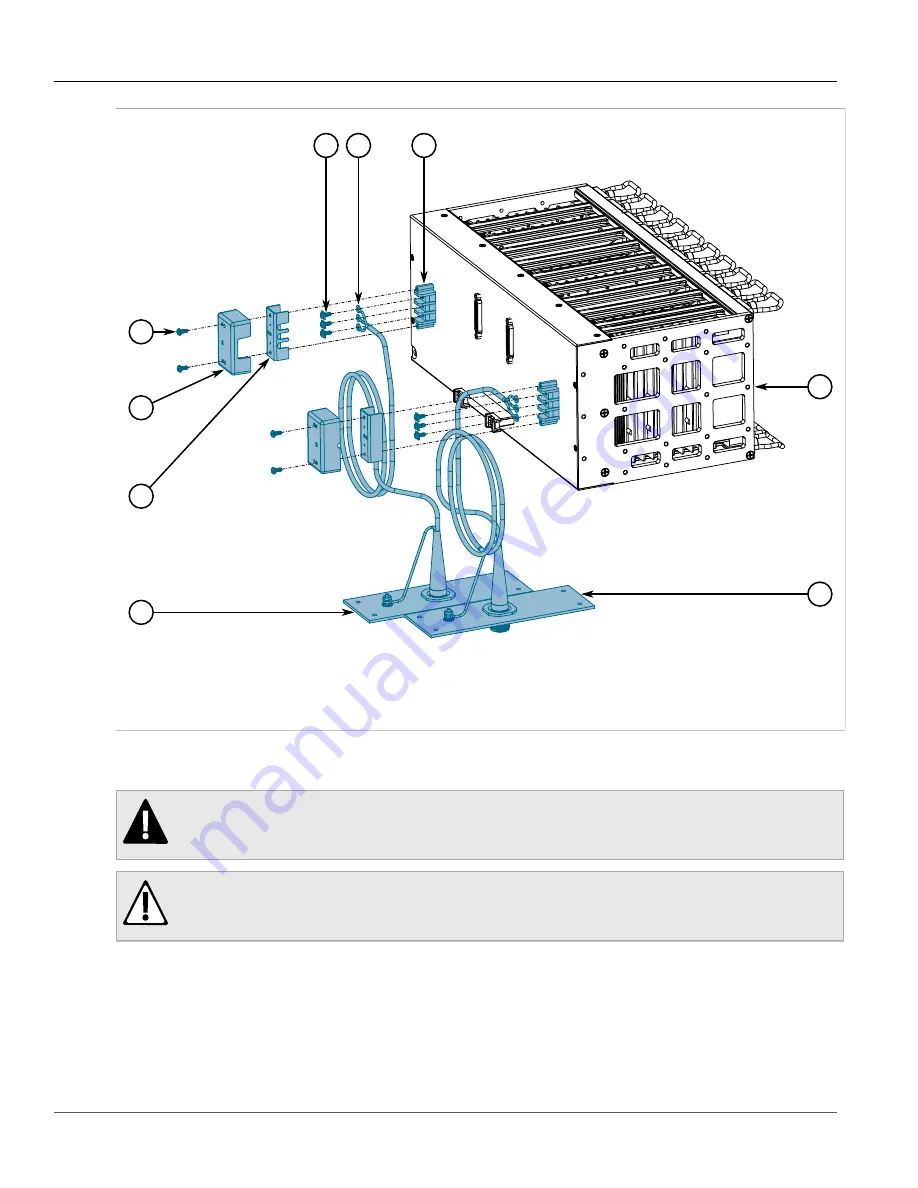
Figure 5: Power Supply Patch Cable Connections

1.

 #6-32×3/8" Pan Head Screw   


2.

 Outer Safety Cover   


3.

 Inner Safety Cover   


4.

 PS1 Cable Assembly   


5.

 Terminal Lug Screws   

6.

 Terminal Ring Lug   


7.

 Terminal Block   


8.

 MX5000   


9.

 PS2 Cable Assembly

2. Remove the outer safety cover and the inner safety cover from the RUGGEDCOM MX5000.
3. Remove the three terminal lug screws from the terminal block.

DANGER!

Electrocution hazard – risk of death, serious personal injury and/or damage to the device. Make

sure the supplied cover is always installed over high voltage screw-type terminal blocks.

CAUTION!

Electrical hazard – risk of damage to equipment. Do not connect AC power cables to a DC power

supply terminal block. Damage to the power supply may occur.

4. Connect the live (+/L) lug from the PS1 cable assembly to the live terminal on the PS1 terminal block.

Содержание RUGGEDCOM MX5000RE

Страница 1: ...RUGGEDCOM MX5000RE Installation Guide 6 2019 RC1060 EN 12 Preface Introduction 1 Installing the Device 2 Device Management 3 Modules 4 Technical Specifications 5 Certification 6 ...

Страница 2: ...and or networks They are important components in a holistic industrial security concept With this in mind Siemens products and solutions undergo continuous development Siemens recommends strongly that you regularly check for product updates For the secure operation of Siemens products and solutions it is necessary to take suitable preventive action e g cell protection concept and integrate each co...

Страница 3: ...RUGGEDCOM MX5000RE Installation Guide iii Industry Sector 300 Applewood Crescent Concord Ontario Canada L4K 5C7 Tel 1 905 856 5288 Fax 1 905 856 1995 Web https www siemens com ruggedcom ...

Страница 4: ...RUGGEDCOM MX5000RE Installation Guide iv ...

Страница 5: ... Optic Cables 6 1 5 Patch Panels 6 1 6 Decommissioning and Disposal 7 Chapter 2 Installing the Device 9 2 1 General Procedure 10 2 2 Unpacking the Device 11 2 3 Installing the Power Supply Patch Cables 11 2 4 Installing the Chassis Ground Connection 13 2 5 Connecting the Failsafe Alarm Relay 14 2 6 Installing the Fan Tray Cables 15 2 7 Installing the Mounting Brackets 17 2 8 Installing the EMI Gas...

Страница 6: ...Removing Line Modules 37 4 3 Installing Removing Power Supply Modules 39 Chapter 5 Technical Specifications 43 5 1 Power Supply Specifications 43 5 2 Failsafe Relay Specifications 43 5 3 Operating Environment 44 5 4 Mechanical Specifications 44 5 5 Dimension Drawings 44 Chapter 6 Certification 47 6 1 Approvals 47 6 1 1 TÜV SÜD 47 6 1 2 European Commission EC 48 6 1 3 FCC 48 6 1 4 FDA CDRH 48 6 1 5...

Страница 7: ...ts Accessing Documentation Training Customer Support Alerts The following types of alerts are used when necessary to highlight important information DANGER DANGER alerts describe imminently hazardous situations that if not avoided will result in death or serious injury WARNING WARNING alerts describe hazardous situations that if not avoided may result in serious injury and or equipment damage CAUT...

Страница 8: ...rs with the essential practical skills to make sure users have the right knowledge and expertise to understand the various technologies associated with critical communications network infrastructure technologies Siemens unique mix of IT Telecommunications expertise combined with domain knowledge in the utility transportation and industrial markets allows Siemens to provide training specific to the...

Страница 9: ...e iOS or Windows mobile device and be able to Access Siemens extensive library of support documentation including FAQs and manuals Submit SRs or check on the status of an existing SR Contact a local Siemens representative from Sales Technical Support Training etc Ask questions or share knowledge with fellow Siemens customers and the support community ...

Страница 10: ...Preface RUGGEDCOM MX5000RE Installation Guide x Customer Support ...

Страница 11: ...ns networking products and provide MIL STD ratings for shock vibration emissions immunity temperature and humidity Ten external patch panels with up to 64 MIL grade round connectors provide tremendous flexibility and allow the enclosure to be employed in many diverse applications A variety of patch panel cable assemblies allow convenient and simple mapping from internal electronics to the outside ...

Страница 12: ...ranges 88 300 VDC or 85 264 VAC Terminal blocks for reliable maintenance free connections CSA UL 60950 1 safety approved to 85 C 185 F Enclosure Features Welded 6061 T4 aluminum extrusion construction Welded 6061 T6 aluminum mounting brackets for MIL901D hard mounting Configurable patch panel allows up to 64 MIL grade circular connectors for both copper and fiber media Integrated cable management ...

Страница 13: ...y USB Port 8 RS232 Serial Console Port DB9 9 Failsafe Alarm Relay 10 CompactFlash Card Port 11 Power Supply Module Indicator LEDs 12 Power Supply Terminal Block When the RUGGEDCOM MX5000RE is configured for rack front mounting these ports controls and LEDs are located on the front panel 4 3 5 6 1 1 2 Figure 2 Front Panel 1 Power Supply Module Indicator LEDs 2 Alarm Indicator LEDs 3 Utility USB Por...

Страница 14: ... information refer to the RUGGEDCOM ROX II User Guide for the RUGGEDCOM MX5000RE Compact Flash Card Port Houses the CompactFlash CF card that contains active and backup installations of RUGGEDCOM ROX II along with the configuration database and other system data For more information refer to Section 3 3 Accessing the CompactFlash Card RS232 Serial Console Port The serial console port is for interf...

Страница 15: ...ient electrical event communications errors or interruptions may occur but recovery is automatic Siemens also does not recommend using copper Ethernet ports to interface with devices in the field across distances that could produce high levels of ground potential rise i e greater than 2500 V during line to ground fault conditions Section 1 4 2 Gigabit Ethernet 1000Base TX Cabling Recommendations T...

Страница 16: ...ct at 90 angles when necessary to reduce inductive coupling Shielded screened cabling can be used when required Care should be taken to avoid the creation of ground loops with shielded cabling Section 1 4 3 Supported Fiber Optic Cables The following fiber optic cable types are supported under the stated conditions Distance m Cable Type Wavelength nm Modal Bandwidth MHz km 100Base FX 1000Base SX 10...

Страница 17: ...rtant to prevent malicious users from obtaining proprietary information and to protect the environment Decommissioning This device may include sensitive proprietary data Before taking the device out of service either permanently or for maintenance by a third party make sure it has been fully decommissioned For more information refer to the associated User Guide Recycling and Disposal For environme...

Страница 18: ...Chapter 1 Introduction RUGGEDCOM MX5000RE Installation Guide 8 Decommissioning and Disposal ...

Страница 19: ...ry This product contains a laser system and is classified as a CLASS 1 LASER PRODUCT Use of controls or adjustments or performance of procedures other than those specified herein may result in hazardous radiation exposure IMPORTANT This product contains no user serviceable parts Attempted service by unauthorized personnel shall render all warranties null and void Changes or modifications not expre...

Страница 20: ...iew all operating and installation instructions before commissioning or performing maintenance on the device 1 Review the relevant certification information for any regulatory requirements For more information refer to Section 6 1 Approvals 2 Review the RUGGEDCOM MX5000RE Modules Catalog https support industry siemens com cs ca en view 109748481 for special installation or regulatory requirements ...

Страница 21: ...nspect the package for damage before opening it 2 Visually inspect each item in the package for any physical damage 3 Verify all items are included IMPORTANT If any item is missing or damaged contact Siemens for assistance Section 2 3 Installing the Power Supply Patch Cables To connect the power supply patch cables to the enclosure do the following 1 Remove the screws from the outer safety cover ...

Страница 22: ... safety cover and the inner safety cover from the RUGGEDCOM MX5000 3 Remove the three terminal lug screws from the terminal block DANGER Electrocution hazard risk of death serious personal injury and or damage to the device Make sure the supplied cover is always installed over high voltage screw type terminal blocks CAUTION Electrical hazard risk of damage to equipment Do not connect AC power cabl...

Страница 23: ...be connected For more information refer to Section 2 4 Installing the Chassis Ground Connection 6 Connect the ground GND lug from the PS1 cable assembly to the ground terminal on the PS1 terminal block 7 If necessary repeat Step 4 to Step 6 to connect the PS2 cable assembly 8 Install the inner and outer safety covers making sure the cables pass through the openings in the sides of the covers 9 Sec...

Страница 24: ...w 3 Grounding Cable 2 Secure the grounding cable and external tooth lock washer to the RUGGEDCOM MX5000 with one pan head screw Torque the screw to 3 4 N m 30 lbf in NOTE The other end of the grounding cable will be connected to the inside of the enclosure in later steps Section 2 5 Connecting the Failsafe Alarm Relay The failsafe relay on the Control Module CM can be configured to latch based on ...

Страница 25: ...Open The failsafe relay terminal is connected to the patch panel for the CM using the cable assembly provided The connector is an Amphenol MIL DTL 38999 size 13 code A The following is the pin out for the connector Figure 10 Failsafe Relay Alarm Panel Connector Pin Description A COM Common B NO Normally Open C NC Normally Closed D Spare Section 2 6 Installing the Fan Tray Cables 1 Apply Loctite 22...

Страница 26: ...11 Fan Tray Cable Connections 1 Fan Cables 2 Attach two fan cables to the terminals on the rear of the RUGGEDCOM MX5000 3 Using two cable ties secure the fan cables and power cables to the cable tie base on the rear of the RUGGEDCOM MX5000 Make sure the cable ties are snug and the cables are unable to slide freely ...

Страница 27: ...alling the Mounting Brackets 17 1 Figure 12 Power and Fan Tray Cable Ties 1 Cable Ties 4 After tightening the cable ties trim and remove any excess length Section 2 7 Installing the Mounting Brackets 1 Position one of the mounting brackets on one side of the RUGGEDCOM MX5000 ...

Страница 28: ...o lengths for the two different sizes of patch panel openings in the RUGGEDCOM MX5000 EMI Gasket Material Length Patch Panel Opening 19 5 D E F and G 35 5 A B C H J and K To install the EMI gaskets do the following 1 Make sure the groove surrounding each panel opening is free of dust dirt or liquid 2 Inspect each gasket for signs of twisting cracking wear or damage If the gaskets need to be replac...

Страница 29: ...et is seated all around the opening and in the overlapping section Make sure the gasket material is loose and is not stretched during installation 2 1 Figure 14 EMI Gasket Installation 4 Trim the gasket material to length 5 Repeat Step 3 and Step 4 for each patch panel opening Section 2 9 Assembling the RUGGEDCOM MX5000 and RUGGEDCOM MX5000RE To install the RUGGEDCOM MX5000 in the RUGGEDCOM MX5000...

Страница 30: ...nded to employee the assistance of another technician 2 Have an assistant hold the attached cables and patch panel clear of the RUGGEDCOM MX5000RE sides 3 Hold the RUGGEDCOM MX5000 by both mount bracket handles and lower it into the RUGGEDCOM MX5000RE 4 Lower the RUGGEDCOM MX5000 unit until the mount bracket flanges are supporting the unit on the inner mount bracket surfaces If the RUGGEDCOM MX500...

Страница 31: ...s the PS2 power supply cable assembly through opening G on the bottom of the RUGGEDCOM MX5000RE NOTE When aligning the patch panels the inside grounding stud should be toward the back of the RUGGEDCOM MX5000RE 10 Apply Loctite 242 to four SS304 truss head philips drive screws 11 Secure both patch panels to the RUGGEDCOM MX5000RE with four SS304 truss head philips drive screws Section 2 10 Installi...

Страница 32: ...and straighten the cables side by side 6 Take the right side fan control cable and thread it through the three 3 loops on the left side of the fan tray 7 Connect the fan control cable to the left side DB25 connector 8 Repeat Step 6 and Step 7 using the left side fan control cable 9 Apply Loctite 222 on the DB25 plug screws Tighten the DB25 connector screws moderately 1 Figure 17 Fan Tray Cable Cli...

Страница 33: ...ning For more information about which patch panels correspond to which openings refer to Section 1 5 Patch Panels 1 2 Figure 18 Patch Panel Installation 1 6 32 5 8 SS304 Truss Head Philips Drive Screw 2 Patch Panel 2 Align the patch panel with the screw holes surrounding the patch panel opening 3 Apply Loctite 242 to each screw 4 Secure the patch panel to the enclosure with eight 8 screws for larg...

Страница 34: ...il the bundled cables are held securely 3 Install additional cable ties where necessary Connecting Ethernet Cables 1 Carefully remove the dust caps from one connector at a time 2 Insert the uncapped connector into the appropriate transceiver on the RUGGEDCOM MX5000 Make sure the cable and port have the same number and the transmit and receive fibers are plugged in to the correct side of the transc...

Страница 35: ...ce of another technician 2 Position the front panel over the RUGGEDCOM MX5000RE opening aligning the panel with the two 2 locating pins on the front face 3 Secure the front panel with 24 screws Hand tighten the screws evenly in a cross pattern Section 2 14 Mounting the RUGGEDCOM MX5000RE To mount the fully assembled RUGGEDCOM MX5000RE to its final mounting surface do the following 1 Make sure the ...

Страница 36: ...hich provides power to both power modules The terminal block is installed using Philips screws and compression plates allowing either bare wire connections or crimped terminal lugs Use 6 size ring lugs for secure reliable connections under severe shock or vibration For information about installing or removing a power module refer to Section 4 3 Installing Removing Power Supply Modules DANGER Elect...

Страница 37: ...t be installed It is recommended to provide a separate circuit breaker for each power module module Equipment must be installed according to applicable local wiring codes and standards CONTENTS Section 2 15 1 Connecting Power to the Enclosure Section 2 15 1 Connecting Power to the Enclosure To complete the power circuit connect an external power supply to the PS1 and or PS2 patch panels using male...

Страница 38: ...Chapter 2 Installing the Device RUGGEDCOM MX5000RE Installation Guide 28 Connecting Power to the Enclosure ...

Страница 39: ...a PC or terminal directly to the serial console or management ports to access the boot time control and ROX II interfaces The serial console port provides access to ROX II s console interface while the management port provides access to ROX II s console and Web interfaces IMPORTANT The serial console and management MGMT ports are intended to be used only as temporary connections during initial con...

Страница 40: ...ss for the RUGGEDCOM MX5000RE is https 192 168 0 2 For more information about available ports refer to Chapter 4 Modules Section 3 2 Configuring the Device Once the device is installed and connected to the network it must be configured All configuration management is done via the RUGGEDCOM ROX II interface For more information about configuring the device refer to the RUGGEDCOM ROX II User Guide a...

Страница 41: ...use with this device Removing the CF card in any scenario other than those described in this section Inserting the CF card To insert the CF card into the device do the following IMPORTANT The device should only be powered on when the CF card is present 1 Make sure the device is powered down 2 Remove the CF card access panel 3 Insert the CF card into the slot until it is fully seated 2 1 Figure 24 ...

Страница 42: ... Guide 32 Accessing the CompactFlash Card 3 2 1 Figure 25 Removing the CF Card 1 Ejector Button 2 CompactFlash Card 3 Access Panel 3 Press the ejector button to the left of the CF card and then pull the card out 4 Secure the CF card access panel to the chassis ...

Страница 43: ... field replaceable Use the RUGGEDCOM ROX II software to determine which ports are equipped on the device For more information refer to the RUGGEDCOM ROX II User Guide for the device NOTE Switch modules are only compatible with 8 port fiber optic Ethernet modules 2 3 4 6 7 8 9 1 5 10 Figure 26 Available Chassis Slots 1 Power Supply Module PS1 2 Ethernet Module Slot LM1 3 Ethernet Module Slot LM2 4 ...

Страница 44: ...GK6050 0ML20 0FD1 Module 6GK6050 0RL20 0FD1 Module with Patch Panel and Cables 6GK6050 0AR00 4RD0 Patch Panel and Cables RUGGEDCOM MX5000REPN LM M8TX02 Specifications Ports 8 Speed 100 Mbps Interface TX Connector Micro D Article Numbers 6GK6050 0ML20 0ND1 Module 6GK6050 0RL20 0ND1 Module with Patch Panel and Cables 6GK6050 0AR00 8RD0 Patch Panel and Cables RUGGEDCOM MX5000REPN LM M12TX01 Specifica...

Страница 45: ...0 Patch Panel and Cables RUGGEDCOM MX5000REPN LM M4FG03 Specifications Mode SM Speed 1000 Mbps Interface LX Wavelength 1310 nm Ports 4 Connector LC Distance 10 Km 6 mi Article Numbers 6GK6050 0ML20 0CR1 Module 6GK6050 0RL20 0CR1 Module with Patch Panel and Cables 6GK6050 0AR00 4SM0 Patch Panel and Cables Serial Modules RUGGEDCOM MX5000REPN LM MS01 Specifications Standard RS232 RS422 RS485 Ports 8 ...

Страница 46: ... Patch Panel and Cables RUGGEDCOM MX5000REPN MSM61 Specifications Layer 3 Article Numbers 6GK6050 0ML40 0VA1 Module 6GK6050 0RL40 0VA1 Module with Patch Panel and Cables 6GK6050 0AR00 0XF0 Patch Panel and Cables RUGGEDCOM MX5000REPN MSM70 Specifications Mode SM Speed 10 Gbps Interface LR Wavelength 1310nm Ports 2 Connector LC Distance 10km 6mi Article Numbers 6GK6050 0ML40 0XA1 Module 6GK6050 0RL4...

Страница 47: ...II For more information refer to the RUGGEDCOM ROX II User Guide for the RUGGEDCOM MX5000RE Once a line module is removed all the features associated with the module are hidden or disabled in RUGGEDCOM ROX II 1 2 3 5 6 7 8 4 Figure 27 Line Modules 1 Ethernet Module Slot LM1 2 Ethernet Module Slot LM2 3 Ethernet Module Slot LM3 4 Control Module CM 5 Switch Module SM 6 Ethernet Module Slot LM4 7 Eth...

Страница 48: ...e screws that secure the module 4 Pull the module from the chassis to disconnect it 1 2 3 Figure 28 Removing a Module 1 Chassis 2 Module 3 Screw 5 Install a new module or a blank module to prevent the ingress of dust and dirt 6 Optional If necessary install the device in the rack 7 For control and switch modules only connect power to the device Installing a Line Module To install a line module do ...

Страница 49: ...s to secure the module 6 Optional If necessary install the device in the rack 7 For control and switch modules only connect power to the device Section 4 3 Installing Removing Power Supply Modules The RUGGEDCOM MX5000 supports dual redundant power supplies that can be installed in any combination 1 2 Figure 30 Power Supply Modules 1 Power Supply Module PS1 2 Power Supply Module PS2 ...

Страница 50: ... module it is not necessary to turn off power to the device Removing a Power Supply Module To remove a power module do the following 1 Loosen the screws that secure the module to the chassis until the module can be removed 3 2 1 Figure 31 Removing a Power Supply 1 Screws 2 Power Supply 3 Chassis 2 Slide the module out of the chassis 3 Install a new or blank module to prevent the ingress of dust an...

Страница 51: ...ply Module 1 Screws 2 Power Supply 3 Chassis 3 Hand tighten the screws to secure the power module to the chassis 4 Turn on power to the device and confirm the module is receiving and supplying power This is indicated by the LEDs on the module LED State Description O Green The module is supplying power I Green The module is receiving power ...

Страница 52: ...Chapter 4 Modules RUGGEDCOM MX5000RE Installation Guide 42 Installing Removing Power Supply Modules ...

Страница 53: ... Min Max Internal Fuse Rating Max Power Consumption a HI 125 250 VDC b 88 VDC 300 VDC HI 110 230 VAC b 85 VAC 264 VAC 6 3 A 250 V T c 110 W d a Power consumption varies based on the device configuration Each 10 100Base Tx port consumes roughly 1 W less than a fiber optic port b The HI power supply is the same power supply for both AC and DC c T denotes time delay fuse Internal fuse is not user rep...

Страница 54: ...mum Altitude 2000 m 6562 ft e Measured from a 30 cm 12 in radius surrounding the center of the enclosure f Operating temperature may vary based on the limitations of installed SFPs Refer to the RUGGEDCOM SFP Transceivers Catalog for SFP temperature ratings g Non condensing Section 5 4 Mechanical Specifications Weight MX5000 14 16 kg 30 35 lbs Weight Enclosure 68 kg 150 lbs Ingress Protection IP64 ...

Страница 55: ...E Installation Guide Chapter 5 Technical Specifications Dimension Drawings 45 Ø 9 65 48 26 71 12 76 20 619 25 76 20 444 50 492 25 625 60 746 25 317 50 458 98 571 50 12 70 71 12 50 80 484 12 Figure 33 Overall Dimensions ...

Страница 56: ...Chapter 5 Technical Specifications RUGGEDCOM MX5000RE Installation Guide 46 Dimension Drawings ...

Страница 57: ...ollowing sections detail the approvals issued for the RUGGEDCOM MX5000RE CONTENTS Section 6 1 1 TÜV SÜD Section 6 1 2 European Commission EC Section 6 1 3 FCC Section 6 1 4 FDA CDRH Section 6 1 5 ISED Section 6 1 6 ISO Section 6 1 7 RoHS Section 6 1 8 Other Approvals Section 6 1 1 TÜV SÜD This device is certified by TÜV SÜD to meet the requirements of the following standards CAN CSA C22 2 NO 60950...

Страница 58: ...sed throughout the European community A copy of the CE Declaration of Conformity is available from Siemens Canada Ltd For contact information refer to Contacting Siemens Section 6 1 3 FCC This equipment has been tested and found to comply with the limits for a Class A digital device pursuant to Part 15 of the FCC Rules These limits are designed to provide reasonable protection against harmful inte...

Страница 59: ...Restriction of Hazardous Substances directives for the restricted use of certain hazardous substances in electrical and electronic equipment China RoHS 2 Administrative Measure on the Control of Pollution Caused by Electronic Information Products A copy of the Material Declaration is available online at https support industry siemens com cs ww en view 109738831 Section 6 1 8 Other Approvals This d...

Страница 60: ...C Type Tests Test Description Test Levels Severity Levels Enclosure Contact 8 kV 4 IEC 61000 4 2 ESD Enclosure Air 15 kV 4 IEC 61000 4 3 Radiated RFI Enclosure Ports 20 V m Note a Signal ports 4 kV 2 5 kHz Note a DC Power ports 4 kV 4 AC Power ports 4 kV 4 IEC 61000 4 4 Burst Fast Transient Earth ground ports 4 kV 4 Signal ports 4 kV line to earth 2 kV line to line 4 DC Power ports 2 kV line to ea...

Страница 61: ...equency Voltage DC Power ports 30 V Continuous 300 V for 1 s 4 IEC 61000 4 17 Ripple on DC Power Supply DC Power ports 10 3 Signal ports 2 kV Fail Safe Relay output DC Power ports 2 kV Dielectric Strength AC Power ports 2 kV Signal ports 5 kV Fail Safe Relay output DC Power ports 5 kV IEC 60255 5 HV Impulse AC Power ports 5 kV a Siemens specified severity levels IEEE 1613 EMC Type Tests NOTE The R...

Страница 62: ...s 5 kV HV Impulse AC Power ports 5 kV Signal ports 2 kV DC Power ports 2 kV Dielectric Strength AC Power ports 2 kV Environmental Type Tests Test Description Test Levels IEC 60068 2 1 Cold Temperature Test Ad 40 C 40 F 16 Hours IEC 60068 2 2 Dry Heat Test Bd 85 C 185 F 16 Hours IEC 60068 2 30 Humidity Damp Heat Cyclic Test Db 95 non condensing 55 C 131 F 6 cycles IEC 60255 21 1 Vibration 2 g 10 15...

Отзывы: