Chapter 1
Introduction
RUGGEDCOM MX5000RE
Installation Guide
4
Required Tools and Materials
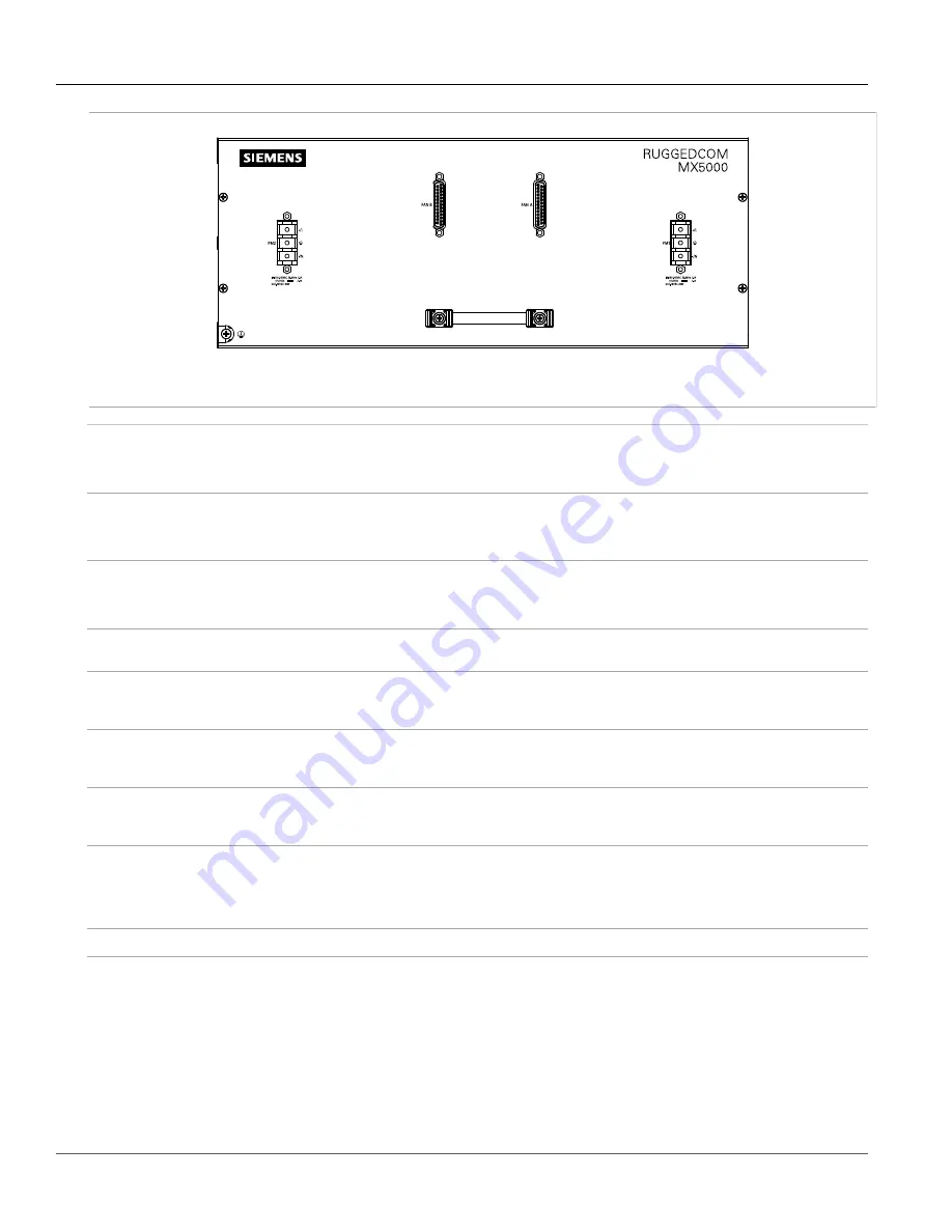
Figure 3: Front Panel – Fan Controller Option
Power Supply Module Indicator LEDs
Indicate the status of the power modules.
• I = The power supply is receiving power
• O = The power supply is supplying power
Alarm Indicator LED
Indicates when an alarm condition exists.
• Green = Alarms cleared/acknowledged
• Red = Alarm
Lamp Test/Alarm Cut-Off (LT/ACO) Button
This button performs two functions:
• Press and hold this button to test all indicator LEDs
• Press and release this button to acknowledge an active alarm
Management Port
This 10/100Base-T Ethernet port is used for system management that is out-of-band from the
switch fabric.
Utility USB Port
Use the USB port to upgrade the RUGGEDCOM ROX II software or install files, such as
configuration files and feature key files. For more information, refer to the
RUGGEDCOM ROX
II User Guide
for the RUGGEDCOM MX5000RE.
Compact Flash Card Port
Houses the CompactFlash (CF) card that contains active and backup installations of
RUGGEDCOM ROX II, along with the configuration database and other system data. For more
information, refer to
Section 3.3, “Accessing the CompactFlash Card”
.
RS232 Serial Console Port
The serial console port is for interfacing directly with the device and accessing initial
management functions. For information about connecting to the device via the serial
console port, refer to
Section 3.1, “Connecting to the Device”
Failsafe Alarm Relay
Latches to default state when a power disruption or other alarm condition occurs. For more
information, refer to:
•
Section 2.5, “Connecting the Failsafe Alarm Relay”
•
Section 5.2, “Failsafe Relay Specifications”
Power Supply Terminal Block
A pluggable terminal block. For more information, refer to
Section 2.15, “Connecting Power”
Section 1.3
Required Tools and Materials
The following tools and materials are required to install the RUGGEDCOM MX5000RE:
Содержание RUGGEDCOM MX5000RE
Страница 4: ...RUGGEDCOM MX5000RE Installation Guide iv ...
Страница 10: ...Preface RUGGEDCOM MX5000RE Installation Guide x Customer Support ...
Страница 18: ...Chapter 1 Introduction RUGGEDCOM MX5000RE Installation Guide 8 Decommissioning and Disposal ...
Страница 38: ...Chapter 2 Installing the Device RUGGEDCOM MX5000RE Installation Guide 28 Connecting Power to the Enclosure ...
Страница 52: ...Chapter 4 Modules RUGGEDCOM MX5000RE Installation Guide 42 Installing Removing Power Supply Modules ...
Страница 56: ...Chapter 5 Technical Specifications RUGGEDCOM MX5000RE Installation Guide 46 Dimension Drawings ...


