4/11
Siemens
Temperature Controller RRV851
CE1N2725en
Building Technologies
27.08.2007
•
Remote room temperature sensing: The QAX850 can be used as a master control
unit without using the built-in temperature sensor. A separate room sensor (QAA32)
can be mounted in a location more convenient for accurate temperature acquisition
•
Return air temperature sensing: A temperature sensor (QAH11.1) can be mounted in
the return air path of the FCU if accurate temperature acquisition in the room is not
possible
•
2-pipe application heating/cooling changeover: For application A8 (2-pipe FCU) a
temperature sensor (QAH11.1/ARG86.3) is clamped to the water pipe in order to
activate heating/cooling mode changeover
The RRV851 controller can be configured for a 1- or 3-speed fan. Voltage-free (SPST)
relay outputs Q74, Q84 and Q94 can switch loads up to AC 250 V, 6 (4) A. Power is
supplied via terminal Q71. The low-speed terminal is used when a 1-speed fan is
configured. On fan startup, high-speed will be activated first for approximately
3 seconds and then resume the selected speed. In Auto Fan mode, the fan speeds will
be activated automatically depending on demand.
For further details on auto fan speed control, refer to the Application Manual.
•
Output Y1: Cooling or compressor output
•
Output Y2: Heating or reversing valve output
•
Output Y3: Auxiliary output that can be configured for auxiliary heating, emergency
heating, 2
nd
step cooling or dual compressor
Output control is 2-position. 3-position modulating can be selected via parameter P17
for applications A1, A2 and A8 only.
Configuration
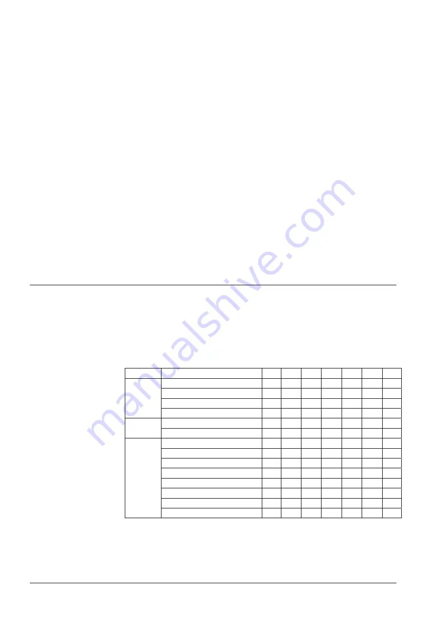
Initial application setup of the RRV851 controller to match the connected HVAC
equipment is made by the selection of DIP switch positions. DIP switches are located
on the top of the controller. An adhesive label is included in the RRV851 packaging box
for the final recording of the DIP switch positions. This can be placed on the DIP switch
block to avoid unauthorized changes. Further parameter settings can be made via the
QAX850 if required.
Function
Selections
1 2 3 4 5 6 7
Auxiliary heating 20 min delay
off off
- - - - -
Auxiliary
heating
10
min
delay
on
off
- - - - -
Emergency
heating
via
D2 off
on
- - - - -
Y3
Auxiliary
output
2
nd
stage
cool
or
compressor
on
on
- - - - -
Single
speed
- - off
- - - -
Fan
speed
Three speed
-
-
on
- - - -
A1
– Heating only
- - -
off off off off
A2
– Cooling only
- - - on off off off
A3
– Cool./(heat. 3 speed fan) - - - off on off off
A4
– Cool./(heat. 1 speed fan) - - - on on off off
A5
– Heat pump (comp + RV) - - - off off on off
A6
– Heat pump (heat/cool)
- - - on off on off
A7
– 4-pipe FCU
- - - off on on off
Applica-
tion
A8
– 2-pipe FCU
- - - on on on off
Default (as delivered) positions are in bold text.
Fan speed outputs
Heat/cool outputs
DIP switches
DIP switch settings


