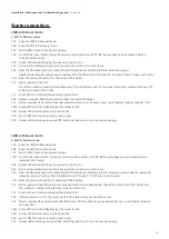
1) LMR-A: Manual mode
a. WLCA- Delivery mode
15A : Check the mode of LMR-A, if it is manual mode.
15B : Check the mode of WLC-A, if it is Delivery mode.
15C : Switches ON the 3-Phase incoming main supply.
15D : Switch ON the rocker switch
15E : Amber LED will start blinking
15F : Amber LED will blink for a duration of min.30sec.
15G : After the ON delay duration, amber LED remains blinking indicating that the 3phase incoming supply is unhealthy.
1
15H : - Check the rated operational voltage of the starter in incoming terminal block (TB1)between L1-
L2 , L2-L3, L1-L3 with suitable equipment e.g. multimeter.
- Check for the phase loss in any phase (L1,L2,L3) with suitable equipment e.g. multimeter.
1
15I : - After resuming incoming main supply to normal condition,
- Repeat the steps from 15A to 15F and then go to step no.15J
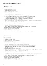
If fault still exists, then
2
15H : - Check the phase sequence of all the phases of incoming main supply.
- Identify the wrong sequence of phase connected in any of the incoming terminal.
2
15I : - Connect the phase sequence of all the phases correctly (R phase to L1, Y phase to L2, B phase to L3) to the incoming
main supply terminals of Terminal block TB1.
- Repeat the steps from 15A to 15F and then go to step no.15J
If fault still exists, then
3
15H : - Check the rated operational voltage of the starter in incoming terminal block (TB1) between
L1-L2, L2-L3, L1-L3 with suitable equipment e.g. multimeter.
- Check whether the 3-phase voltage in the incoming terminals of terminal block TB1 is <minimum required voltage
(Refer table no.28).
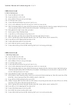
3
15I : - Keep the 3-phase voltage to the incoming terminals of terminal block TB1 to a voltage between
min.required voltage & Max.voltage allowed (Refer table no.28).
- Repeat the steps from 15A to 15F and then go to step no.15J
If fault still exists, then
4
15H : - Check the rated operational voltage of the starter in incoming terminal block (TB1) between L1-L2, L2-L3, L1-L3 with
suitable equipment e.g. multimeter.
- Check whether the 3-phase voltage in the incoming terminals of terminal block TB1 is >Maximum voltage allowed.
(Refer table no.28).
4
15I : - Keep the 3-phase voltage to the incoming terminals of terminal block TB1 to a voltage between
min.required voltage & Max.voltage allowed (Refer table no.28).
- Repeat the steps from 15A to 15F and then go to step no.15J
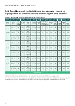
If fault still exists, then
5
15H : - Check the rated operational voltage of the starter in incoming terminal block (TB1) between L1-L2, L2-L3, L1-L3.
- Check whether the operational line voltage difference between any 2 phase in the incoming. terminals of terminal block
TB1 is >50V.
5
15I : - Starter will be operational only if the incoming supply voltage difference between any 2 phase in
the incoming terminal block TB1 of the starter is <=50V.
- Repeat the steps from 15A to 15F and then go to step no.15J
6
Note: Amber LED willnot blink or provide any indication for the misplacement of sensors in the Delivery & suction tank.
Please follow the below steps for the corrective action of any fault which may arise due to the
misplacement of sensors in the delivery tank.
6
15H : - Check if the P2, P3 sensors of delivery tank are in water.
6
15I : - If yes, then keep P2, P3 sensors out of water for operating the starter.
- Repeat the steps from 12K to 12N
Starter Fault conditon:
Installation, Maintenance & Troubleshooting guide
| Version 05
20
Содержание Raja+ 3TE7431- 2CC25-1A Series
Страница 1: ...Installation Maintenance Troubleshooting Guide For RAJA Agriculture Starters Controllers ...
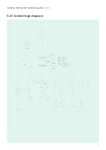
Страница 6: ...5 21 Control logic diagram 6 Installation Maintenance Troubleshooting guide Version 05 ...
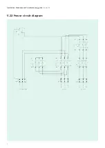
Страница 7: ...Installation Maintenance Troubleshooting guide Version 05 5 22 Power circuit diagram 7 ...

