Installation:
• Open the door by unscrewing the door knob.
• Mount the controller on a vertical wall / plate free from
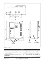
vibrations with proper nuts and bolts. Refer Fig. 5 for
mounting dimensions.
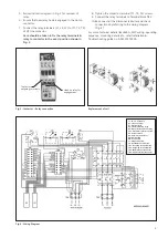
• Remove the rubber grommets for the incoming and
outgoing cable connections. (Refer Fig. 2).
• Connect incoming and outgoing cables as follows
(Refer Fig. 2):
– Use proper cable glands to ensure dust proofing. For
conduit entry use packed washers.
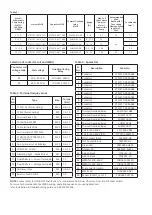
– Select correct size of cables from Table 1.
– Remove approx. length of insulation as per following
table:
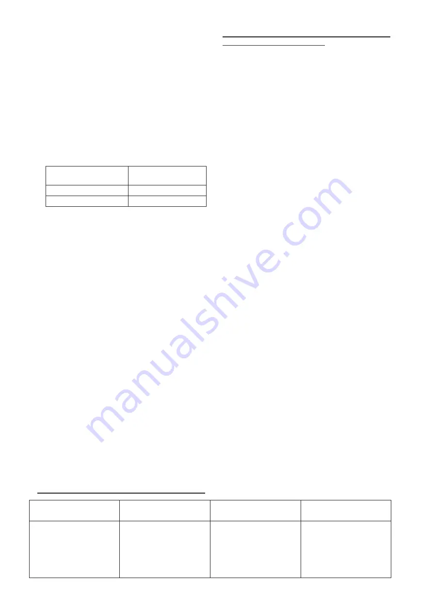
Length of insulation
removal (mm)
Cu cable size
(mm
2
)
6
2.5
5
1.5
– Connect line and motor cables exactly as per wiring
diagram pasted inside the cover of the starter.
– Terminate the incoming supply cables on terminal
block TB1 & outgoing cables to motor on terminal
block TB2 (Tightening torque - Refer table 2).
NOTE:
LMRA is set in Manual mode (Factory setting)
WLC is set in Delivery mode (Factory setting)
• Set the overload relay scale (Fig. 2) using proper screw
driver as follows:
– Set the overload relay to rated current mentioned on
motor name plate.
– Press green button of the contact block CB1 (Fig. 2)
to start the motor and wait till it reaches to normal
speed. Reduce the overload relay settings till it trips.
– Set the overload relay at slightly higher value.
– Allow a reset time appr. 4min. and reset the overload
relay manually.
– Restart the motor. If the relay does not trip, consider
the overload relay as properly set.
If it trips, set it at little higher value and recheck.
– Press the red knob (Fig. 2) on the overload relay to
stop the motor.
– Close the door by screwing the door knob.
Procedure for connecting WLC sensors & terminations:
• These sensors need to be routed from left side of Base
plate through cable gland (Please ensure due care to
avoid damage to the sensors.)
Caution:
•
During commissioning or maintenance always ensure
that the main supply is disconnected by switching off
the main switch & Rocker switch.
• If the relay trips even when set at rated motor current
the suitability of the controller/relay for the particular
application should be checked with the nearest Siemens
office.
Operation:
• Ensure the door is locked.
• Rotate the Mechanical Latch away from OFF push button.
• Switch On the rocker switch marked ‘I’.
• Check the status of amber LED. Wait till amber LED is
continuously ON then only proceed.
• Depending upon Selector switch knob position for phase
selection, Indication of incoming power supply voltage
can be seen on Dual VA meter.
• For starting the motor, press Green push button marked
‘I’ (Fig. 1).
• Line current of R phase is indicated by Dual VA meter.
• Motor is ON when green LED is ON.
• For stopping the motor press Red push button marked ‘O’
(Fig. 1).
• For LMRA Auto / Bypass modes, refer troubleshooting
guide A5E50797230A.
• For WLC Delivery / Suction / Dual tank modes, refer
troubleshooting guide A5E50797230A.
• Reset Operation
– If the overload relay trips, Reset manually. (Allow a
reset time of approx. 4 min.)
Maintenance:
• Switch off the Controller and Put Latch on the OFF push
button, (marked ‘O’).
Disconnect the main supply by
switching the main switch & Rocker Switch Off before
doing any maintenance.
• Keep the interior dust free.
• Re-tighten the terminal screws from time to time as per
specified torque in table 2.
• No maintenance is needed for overload relay. Please do
not open the relay.
• Replace contacts of the contactor if they were severely
pitted or when only 40% of the original contact tips
remains.
• Replacement of Overload Relay (Refer Fig. 3):
1. Select a proper relay exactly as per the original.
2. Slightly loosen the outgoing terminal screws of the
relay.
3. Disconnect the wires connected to the relay terminals.
4. Slightly loosen the outgoing terminal screws of the
contactor.
Mode
For Single Tank application
(Delivery or Suction mode)
For Dual Tank application
(Dual tank mode)
For by passing WLC
Connection Procedure
Connect sensors P1, P2 &
P3 to Terminal X1, X2, X3 of
Terminal block TB5
Connect sensors P1, P2
& P3 to Terminal X1, X2,
X3 of Terminal block TB5
& sensors P4, P5 & P6 to
Terminal X4, X5, X6 of
Terminal block TB5
Remove connection
between X7-X8 of Terminal
block TB5.
Remove connection from
X11 of TB5 & Connect it to
X12 of TB5.
2


