


15
PAD-4 Installation, Operation and Maintenance Manual
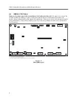
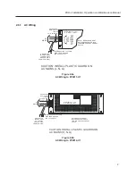
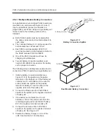
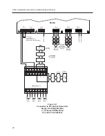
2.6.5
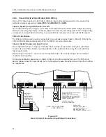
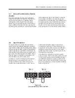
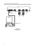
Auxiliary Power Supply Output
The auxiliary power supply output provides a 24VDC power source. It is supervised for ground fault and
short and is power limited. This output is limited to 3.0 amps maximum.
TB15
NAC3B
NAC4B (NAC2A)
_
+
_
+
1
1
TB16
AUX PWR SUPPLY
_
+
DO
NOT
USE
DO
NOT
USE
AUXILIARY POWER OUTPUT
3A MAX., 24VDC, SPECIAL APPLICATION
(REFER TO SECTION 1.3
GENERAL SPECIFICATIONS)
SUPERVISED, POWER LIMITED
Figure 2-14
Auxiliary Power Supply Output Connection
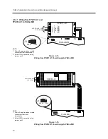
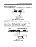
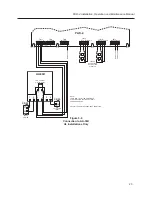
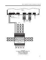
2.6.6
Common Trouble Relay
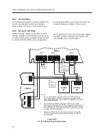
The PAD-4 board has a Form C trouble relay. The relay will de-energize under a trouble condition.
A typical application of the trouble relay is to connect the PAD-4 normally closed (N.C.) contacts in
series with an EOL of a spare IDC or NAC or monitor input from a fire alarm control unit. This will cause
a trouble on the fire alarm control unit when the PAD-4 opens its trouble contacts.
For AC Fail reporting, refer to Section 5.1.4 for configuration and response times.
Note: The N.C. contact is the relay contact that is closed when the PAD-4 has power and there are no
trouble conditions.
TB11
1+
1-
2+
1
1
1
TB12
TB13
TB14
NAC1B
NAC2B (NAC1A)
_
+
_
+
NC COM NO
NC
COM
2-
2
1
1
+
-
IDC EOL
(SEE CONTROL UNIT
INSTALLATION INSTRUCTIONS)
CONTROL UNIT
IDC CONNECTION
INITIATING CIRCUIT
TROUBLE RELAY CONTACT
(SHOWN IN NORMAL
STANDBY CONDITION)
2A @ 30VDC,
RESISTIVE FOR POWER
LIMITED SOURCE
UNSUPERVISED
DO
NOT
USE
INPUT 1
INPUT 2
Figure 2-15
Trouble Relay Connection Example