background image

Technical Instructions  

OpenAir

™ GLB Enhanced Non-Spring Return Rotary Electronic Damper Actuator 

Document Number 155-785 
January 20, 2017 


Page 12 

Siemens Industry, Inc. 


Wiring, Continued 

GLB34x 
100 to 240 Vac Power Supply, Two-Position 
Floating Control 

Each wire has the standard symbol printed on it. See 
Table 4. 


Figure 22.  GLB34x Wiring. 


Figure 23.  2-Position, SPST 
(Single-Pole, Single-Throw). 


Figure 24.  2-Position, SPDT 

(Single-Pole, Double-Throw). 

Table 4.  Two-Position, Floating Control, 100 to 240 Vac. 

Standard 

Symbol 

Function 

Terminal 

Designation 

Color 

Supply (SP) 

Light Blue 

Control signal 
clockwise 

Y1 

Black 

Control signal 
counterclockwise 

Y2 

White 

Factory-installed Options


S1 

Switch A 
Common 

Q11 

Gray/Red 

S2 

Switch A - NC 

Q12 

Gray/Blue 

S3 

Switch A - NO 

Q14 

Gray/Pink 

S4 

Switch B - 
Common 

Q21 

Black/Red 

S5 

Switch B - NC 

Q22 

Black/Blue 

S6 

Switch B - NO 

Q24 

Black/Pink 


Figure 25.  Floating Control, 100 to 240 Vac. 


Table 5.  Modulating Control, 24 Vac/dc.


GLB 16x 

24 Vac/dc Power Supply, 0(2) 
to 10V Modulating Control


Standard 

Symbol 

Function 

Terminal 

Designation 

Color


Supply (SP) 

Red 

Neutral (SN) 

G0 

Black 


Figure 26.  GLB16x Wiring. 

0(2) to 10 Vdc input signal 

Gray 

Output for 0(2) to 10 Vdc 
position indication 

Pink 

Factory-installed Options 

S1 

Switch A Common 

Q11 

Gray/Red 

S2 

Switch A - NC 

Q12 

Gray/Blue 

S3 

Switch A - NO 

Q14 

Gray/Pink 

S4 

Switch B - Common 

Q21 

Black/Red 

S5 

Switch B - NC 

Q22 

Black/Blue 

S6 

Switch B - NO 

Q24 

Black/Pink 
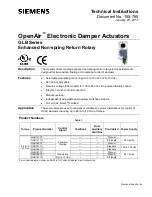


Содержание OpenAir GLB Series

Страница 1: ...ch conduit connection Manual override Independently adjustable dual auxiliary switches available cUL and UL listed certified Application These actuators are used in constant or variable air volume installations for control of HVAC dampers requiring up to 88 lb in 10 Nm of torque Product Numbers Table 1 Torque Product Number Control Signal Feedback Dual Auxiliary Switches Pre Cabled Power Supply 88...

Страница 2: ...o UL cUL Class III per EN60730 Auxiliary features Dual auxiliary switch contact rating 4A resistive 2A inductive Voltage GLB1xx 1P 24 Vac 24 Vdc GLB34x 1U 250 Vac DC rating 12 to 30 Vdc DC 2A Switch Range Switch A 0 to 90 with 5 intervals Recommended range usage 0 to 45 Factory setting 5 Switch B 0 to 90 with 5 intervals Recommended range usage 45 to 90 Factory setting 85 Switching hysteresis 2 Fu...

Страница 3: ...ection 18 AWG Standard cable length 3 ft 0 9 m Life cycle Designed for 100 000 full strokes and 5 million repositions at rated torque and temperature Actuator Dimensions inches mm 6 6 L 2 8 W 2 4 D 166 7 L 71 W 61 D Packaging Dimensions inches mm 6 5 L 10 3 W 3 1 D 165 1 L 261 1 W 78 7 D Weight 1 35 lb 0 61 kg with packaging 1 91 lb 0 87 kg Accessories NOTE The auxiliary switches cannot be added i...

Страница 4: ...inch 8 to 10 mm diameter shafts 10 pk Included in box with GDE GLB Series NOTE Factory installed 1 2 inch guide must be removed prior to installation Figure 6 1 2 inch Shaft Guide 985 101P25 Shaft guide 1 2 inch 25 pk Factory installed with GDE GLB Series Figure 7 NEMA Type 4X Weather Shield ASK75 7U GLB Actuators are UL listed to meet NEMA Type 4X requirements a degree of protection against falli...

Страница 5: ... Figure 8 Parts of the Actuator Legend 1 Base plate 2 Positioning scale for angle of rotation 3 Rotation direction adjustment 4 Conduit adapter 5 Connection cable 6 Manual override 7 Coupling bushing 8 Factory installed 1 2 inch guide 9 Auxiliary Switch A 10 Auxiliary Switch B 11 Position indicator 12 Adjustment lever with locking screw 4 mm hex 13 Set screw for mechanical range stop 4 mm hex 14 M...

Страница 6: ...dicator 13 Adjustment lever with locking screw 4 mm hex 14 Set screw for mechanical range stop 4 mm hex 15 Mounting bracket Operation A continuous 0 to 10 Vdc or 2 to 10 Vdc signal from a controller to wire 8 Y operates the damper actuator The angle of rotation is proportional to the control signal A 0 2 to 10 Vdc position feedback output signal is available between wire 9 U and wire 2 G0 to monit...

Страница 7: ...etting interval 5 Switching hysteresis 2 Actuator Scale Counterclockwise Figure 10 Adjustable Switching Values for the Dual Auxiliary Switches NOTE The auxiliary switch setting shafts rotate with the actuator The scale is valid only when the actuator is in the 0 position on clockwise motion Use the long arm of the AUX SWITCH ADJUSTMENT to point to the position of Switch A Use the narrower tab on t...

Страница 8: ...o the UP 2 10 position Self adapt Switch Figure 14 OFF Position Factory Setting The factory setting is 0 OFF When mechanical angle of rotation is limited the self adapt switch middle DIP switch may be turned ON so that the limited range will become the new 0 to 100 for the actuator logic In this case 0 to 100 is not equal to 90 CAUTION When turning the self adaptive feature on or after the softwar...

Страница 9: ...actuator type from Table 3 Table 2 Total Torque Actuator 44 lb in 5 Nm GDE 88 lb in 10 Nm GLB 132 lb in 15 Nm GEB 221 lb in 25 Nm GBB 310 lb in 35 Nm GIB 310 lb in 620 lb in 35 Nm to 70 Nm Use tandem mounting bracket ASK73 1 with any GIB1x actuator Mounting and Installation Place the actuator on the damper shaft so that the front of the actuator is accessible The label is on the front side A mount...

Страница 10: ...blade do the following 1 Loosen the stop set screw 2 Move the screw along the track to the desired position and fasten it in place Figure 17 Moving the Mechanical Range Stop To use the entire 0 2 to 10V input signal to control the mechanically limited range see Figure 14 for setting self adaptive features Example Stop set screw at 70 Self adapt switch ON Input signal Y 5 Vdc The damper will be at ...

Страница 11: ...8 They must be rated for 100 duty cycle Over current protection for supply lines is maximum 10A Wiring Each wire has the standard symbol printed on it See Table 3 GLB14x 24 Vac dc Power Supply 2 Position Floating Control Figure 18 GLB14x Wiring Diagram Figure 19 2 Position SPST Single Pole Single Throw Figure 20 2 Position SPDT Single Pole Double Throw Table 3 2 Position Floating Control 24 Vac dc...

Страница 12: ...ontrol signal counterclockwise Y2 White Factory installed Options S1 Switch A Common Q11 Gray Red S2 Switch A NC Q12 Gray Blue S3 Switch A NO Q14 Gray Pink S4 Switch B Common Q21 Black Red S5 Switch B NC Q22 Black Blue S6 Switch B NO Q24 Black Pink Figure 25 Floating Control 100 to 240 Vac Table 5 Modulating Control 24 Vac dc GLB 16x 24 Vac dc Power Supply 0 2 to 10V Modulating Control Standard Sy...

Страница 13: ...ld indicate open circuit or no resistance 3 Apply a control signal 24 Vac dc to wires 1 red and 6 violet The DMM should indicate contact closure as the actuator shaft coupling reaches the setting of Switch A 4 Stop applying the control signal to wires 1 red and 6 violet 5 Connect wires S1 and S2 to the DMM The DMM should indicate open circuit or no resistance 6 Apply a control signal 24 Vac dc to ...

Страница 14: ...to 240 Vac to wires 4 light blue and 6 black The DMM should indicate contact closure as the actuator shaft coupling reaches the setting of Switch A 4 Stop supplying the control signal to wires 4 light blue and 6 black 5 Connect wires S1 and S2 to the DMM The DMM should indicate open circuit or no resistance 6 Apply a control signal 100 to 240 Vac to wires 4 light blue and 7 white The DMM should in...

Страница 15: ... coupling returns to the 0 position Check Auxiliary Switch A 1 Set the DMM dial to ohms resistance or continuity check 2 Connect wires S1 and S3 to the DMM The DMM should indicate open circuit or no resistance 3 Apply a full scale input signal to wire 8 gray The DMM should indicate contact closure as the actuator shaft coupling reaches the setting of Switch A 4 Connect wires S1 and S2 to the DMM T...

Страница 16: ...roduct or company names mentioned herein may be the trademarks of their respective owners 2017 Siemens Industry Inc Siemens Industry Inc Building Technologies Division 1000 Deerfield Parkway Buffalo Grove IL 60089 USA Tel 1 847 215 1000 Your feedback is important to us If you have comments about this document please send them to sbt_technical editor us sbt siemens com Document No 155 785 Printed i...

Отзывы: