


4
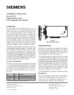
Figure 5
NCC-2F HNET Connections
5
NCC-2F
TB1
2
3
4
*
*
1
NETWORK A
(PRIMARY)
SUPERVISED
NETWORK A
(PRIMARY)
SUPERVISED
NETWORK B
(SECONDARY)
SUPERVISED
OMIT THIS PAIR
FOR STYLE 4
1
2
3
4
5
6
7
8
9
10
11
12
13
14
15
16
ONE SLOT OF CC-5
NIC-C
* EOLR 120 OHMS, 1/2W, 5%
P/N 140-820350
NOTES:
1. The screw terminals can accommodate one
12-24AWG or two16-24AWG.
2. From the NCC-2F to NIC-C:
2000 feet (33.8 ohms) max. per pair between
CC-5s/CC-2s.
Unshielded twisted pair
.25
μ
F max. line to line
Shielded twisted pair
.15
μ
F max. line to line
.2
μ
F max. line to shield
3. Use twisted pair or twisted shielded pair.
4. Terminate shields at one and only one NIC-C.
5. Power limited to NFPA 70 per NEC 760.
6. Maximum voltage 8V P-P.
7. Maximum current 75mA during message
transmission.
8. Each pair independently supervised.
9. Positive or negative ground fault detected at
<10K ohms on pins 1-2, 3-4, 5-6, 7-8 of the
NIC-C.
Figure 6
NCC-2F-HNET-VNT Wiring on FCC Only
NOTES:
1. The screw terminals can
accommodate one 12-24AWG
or two16-24AWG.
2. From the NCC-2F to NIC-C:
2000 feet (33.8 ohms) max.
per pair between CC-5s/CC-2s.
Unshielded twisted pair
.25
μ
F max. line to line
Shielded twisted pair
.15
μ
F max. line to line
.2
μ
F max. line to shield
3. Use twisted pair or twisted shielded pair.
4. Terminate shields at one and only one NIC-C.
5. Power limited to NFPA 70 per NEC 760.
6. Maximum voltage 8V P-P.
7. Maximum current 75mA during message transmission.
8. Each pair independently supervised.
9. Positive or negative ground fault detected at <10K ohms on pins 1-2, 3-
4, 5-6, 7-8 of the NIC-C.
10. For Style 4, remove jumper P2 on all NIC-Cs except on the NIC-C that is
connected to the NCC-2F card. For Style 7, remove jumpers P2 and P4 on
all NIC-Cs except on the NIC-C that is connected to the NCC-2F card.
1
2
3
4
5
6
7
8
9
10
11
12
13
14
15
16
17
18
19
20
21
22
23
24
SEE NOTE 7
DO NOT USE
DO NOT USE
DO NOT USE
DO NOT USE
ONE SLOT OF CC-5/CC-2
FIRST NIC-C
1
2
3
4
5
6
7
8
9
10
11
12
13
14
15
16
17
18
19
20
21
22
23
24
SEE NOTE 7
DO NOT USE
DO NOT USE
NETWORK A
(PRIMARY)
SUPERVISED
ONE SLOT OF CC-5/CC-2
1
2
3
4
5
6
7
8
9
10
11
12
13
14
15
16
17
18
19
20
21
22
23
24
SEE NOTE 7
DO NOT USE
DO NOT USE
ONE SLOT OF CC-5/CC-2
LAST NIC-C
NCC-2F
2
3
4
*
1
NETWORK A
(PRIMARY)
SUPERVISED
* EOLR 120 OHMS, 1/2W, 5%
P/N 140-820350
DO NOT USE
DO NOT USE
*
* EOLR 120 OHMS, 1/2W, 5%
P/N 140-820350
*
5
TB1
*
NETWORK B
(SECONDARY)
SUPERVISED
OMIT THIS PAIR
FOR STYLE 4