Siemens ISOLATED MULTI-DROP SG-6048-01 Скачать руководство пользователя страница 5

Setting Up the Converter

2

 Siemens 

Energy 

Automation, 

Inc.

2 Setting Up the Converter

2.1

Overview

Before connecting the converter to your system, understand
the connectors, LEDs and switches. This section describes
each of the following features according to their functions: 

four RS-485 communications ports

one RS-232 communications port

power module

three configuration switches for communications

manual and automatic operating modes

2.2

RS-485 Communications Ports

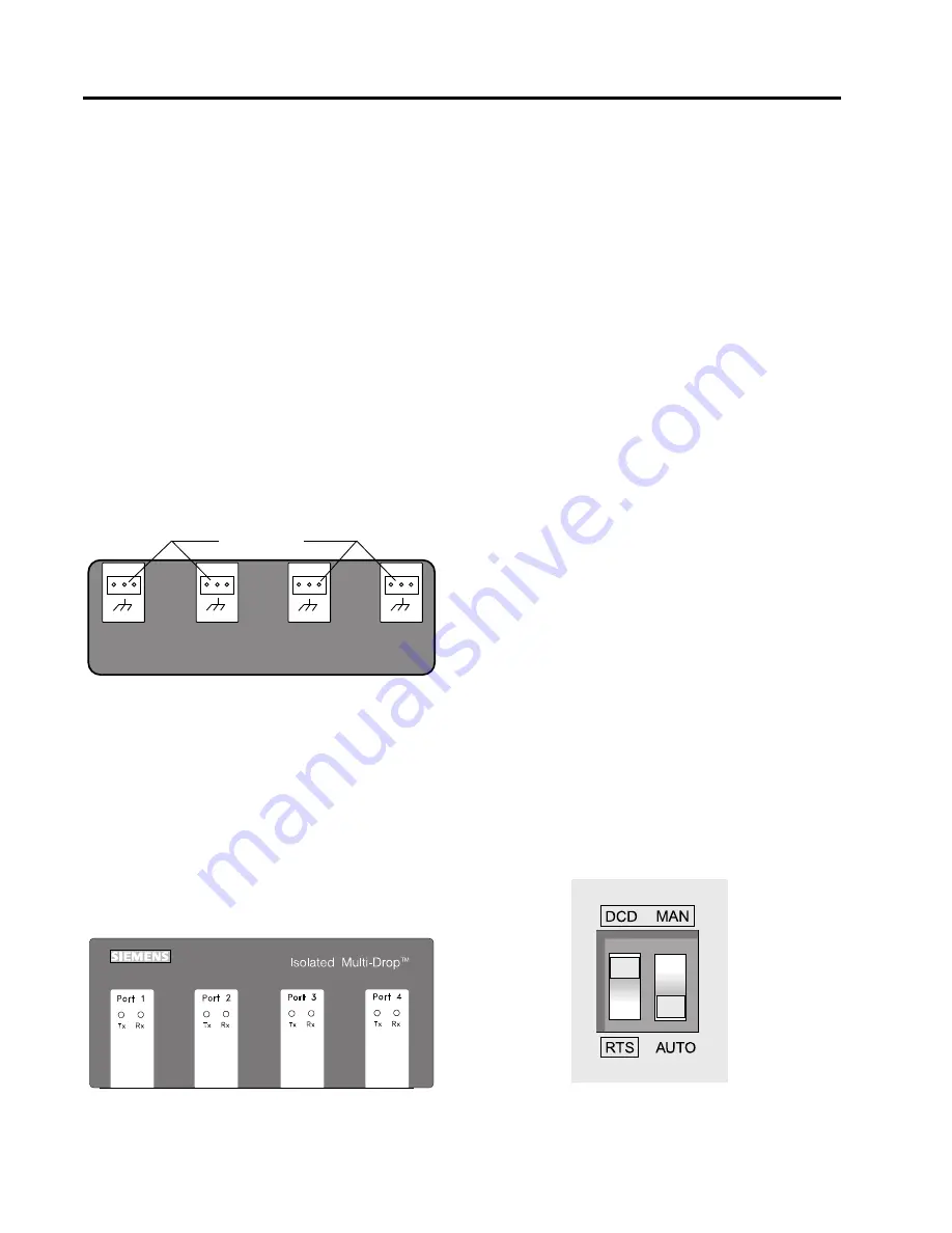
The Isolated Multi-Drop converter is equipped with four 
RS-485 ports located on the converter’s front panel, 
as illustrated in Figure 2.1

Figure 2.1 

Connectors on Front Panel

Each port allows you to connect as many as 32 field devices
on a single RS-485 communications cable; however, your
application software may limit the number of devices your
system can accommodate. Each port has Data(+) and 
Data(-) terminals and a ground terminal for the cable shield. 

For diagnostics, each port is equipped with a yellow
transmit (Tx) LED and a green receive (Rx) LED, located on
top of the device. The Tx LEDs blink during the transmission
of data, which occurs on all ports simultaneously; only one
Rx LED blinks when data is received. The LEDs are
illustrated in Figure 2.2

Figure 2.2 

Communications LEDs on the Top Panel

+

_

RS485

RS485

RS485

RS-485 receptacles

RS485

+

_

+

_

+

_

2.3

RS-232 Communications Port

The converter is equipped with one RS-232
communications port located on the rear panel, as
illustrated in Figure 2.4. This port lets you connect the
converter to a PC for desktop operation, or to a short-haul
or dial-up modem for remote operation.

2.4

Power Module

The interface of the converter’s power module is located on
the rear panel, as illustrated in Figure 2.4. The power
module includes an ON/OFF switch, an indicating power
(PWR) LED, a 120 VAC power input, and a 15 VDC power
output. The 15 VDC output is used to provide power to
Static Trip III

TM

 trip units and SAMMS

TM

 motor control and

protection relays during testing. The filtered input next to the
power switch is for providing line power to the converter.
The power switch turns the converter on and off, and the
PWR LED illuminates when the converter is turned on.

2.5

Configuration Switches

On the rear panel are the converter’s three configuration
switches, collectively labeled “TX CONTROL”. Set these
switches before operating the converter. Refer to Figure 2.4
for the location of these switches. The two switches, labeled
DCD/RTS and MAN/AUTO, and one thumbwheel switch,
labeled BAUD are described below. This section describes
the uses of each configuration switch in more detail.

2.5.1

TX CONTROL Switches

The MAN/AUTO switch places the Isolated Multi-Drop
converter in either manual or automatic operating mode,
both of which are described below. Your application
software determines which mode you should use. 

The DCD/RTS switch is set according to the method of data
transmission for your configuration. Set the switch to DCD
for the Data Carrier Detect (DCD) circuit (pin 8, RS-232
cable) to send a message to the PC when a proper carrier
signal is received. Set the switch to RTS for the Request To
Send (RTS) circuit (pin 4, RS-232 cable) to send a message
to the converter requesting permission to send data on the
Tx Data circuit (pin 2, RS-232 cable). Figure 2.3 shows the
switches set to DCD and AUTO. 

Figure 2.3 

Tx Control Switches

Содержание ISOLATED MULTI-DROP SG-6048-01

Страница 1: ...Isolated Multi Drop Converter Operator s Manual Manual No SG 6048 01 LOGO Isolated Multi Drop Port 1 Tx Rx Port 4 Tx Rx Port 3 Tx Rx Port 2 Tx Rx RS485 RS485 RS485 RS485 ...

Страница 2: ...D PERSON For the purposes of this manual a qualified person is one who is familiar with the installation construction or operation of the equip ment and the hazards involved SUMMARY These instructions do not purport to cover all details or variations in equipment nor to provide for every possible contingency to be met in connection with installation operation or maintenence Should further informat...

Страница 3: ...reparing the RS 485 Cable 4 3 3 Connecting Directly to a PC 5 3 4 Connecting with Short Haul Modems 6 3 5 Connecting with Dial Up Modems 7 4 Testing ACCESS Devices 8 4 1 Prepare Cable 8 4 2 Testing Static Trip III in Type RL Circuit Breaker 8 4 3 Testing Static Trip III on Desktop 9 4 4 Testing SAMMS on Desktop 9 5 Troubleshooting 11 Appendix A Block Diagram Appendix B Mounting Dimensions ACCESS I...

Страница 4: ...rt on your computer The Isolated Multi Drop converter also protects the PC from field device potentials by providing opto isolators between the RS 232 and RS 485 interfaces To isolate the PC further the converter is equipped with high energy surge suppression that meets or exceeds ANSI C62 41 IEEE 587 standards The converter also incorporates isolated DC DC converters that provide electrical isola...

Страница 5: ... up modem for remote operation 2 4 Power Module The interface of the converter s power module is located on the rear panel as illustrated in Figure 2 4 The power module includes an ON OFF switch an indicating power PWR LED a 120 VAC power input and a 15 VDC power output The 15 VDC output is used to provide power to Static Trip IIITM trip units and SAMMSTM motor control and protection relays during...

Страница 6: ...UTO switch must be set to MAN and the DCD RTS switch must be set to RTS When the Isolated Multi Drop converter is installed at a remote location using short haul modems the MAN AUTO switch must be set to MAN and the DCD RTS switch must be set to DCD Short haul modems typically pass RTS through on the DCD pin at the remote modem 2 5 3 Operating in Automatic Mode Set the converter to automatic mode ...

Страница 7: ...o the latest revision of the ACCESS System Installation Guide Manual No SG 6028 3 2 Preparing the RS 485 Cable The converter comes with four connectors to connect your system s RS 485 cable to the converter Use these connectors to connect as many as four cable runs to the converter s four RS 485 ports To install connectors on RS 485 cable follow these instructions and refer to Figure 3 1 1 Strip t...

Страница 8: ...TS control set the MAN AUTO switch to AUTO and use the BAUD thumbwheel to set the data rate to match that of the application software and the ACCESS devices on the network In automatic mode the converter ignores the setting of the DCD RTS switch Figure 3 2 Connecting the Converter Directly to a PC Table 3 1 RS 232 Pin Assignments Pin Number on Connector Signal Name 2 TxD 3 RxD 4 RTS 7 GND 8 DCD SH...

Страница 9: ... s manual 2 If you re using application software that requires direct DCD RTS control set the DCD RTS switch to DCD and the MAN AUTO switch to MAN If you are using application software that does not require direct DCD RTS control set the MAN AUTO switch to AUTO and use the BAUD thumbwheel to set the data rate to match that of the application software and the ACCESS devices on the network In Automa...

Страница 10: ...Figure 3 5 3 Set the MAN AUTO switch to AUTO and use the BAUD thumbwheel to set the data rate to match that of the application software and the ACCESS devices on the network In Automatic mode the converter ignores the setting of the DCD RTS switch Figure 3 4 Connecting the Converter with Dial Up Modems SHLD SHLD SHLD SHLD Port 4 Port 3 Port 2 Port 1 Device n Device 1 PC with Supervisory Software R...

Страница 11: ...eps to connect the trip unit to the converter for 15 VDC power while referring to Figure 4 2 1 Plug the connector of the two conductor cable into the 15 VDC output port 2 Making sure to observe the polarity of the cable connect the other end to terminals 2 and 3 on the terminal block for cubicle disconnect This terminal block is located on the inside left panel of the Type RL circuit breaker compa...

Страница 12: ... 10 4 4 Testing SAMMS on Desktop If you are testing a SAMMS device on a desktop follow these steps to connect the device to the converter while referring to Figure 4 4 on the next page and to the SAMMS LV User s Manual Manual No MC 3298 or SAMMS MV User s Manual Manual No MVC 9108 1 Prepare 2 two conductor cables by connecting them to one two terminal connector as described at the beginning of thi...

Страница 13: ...4 4 Connecting SAMMS Device for Testing Two wire cable RS 485 cable rear panel front panel 15VDC OUT RS485 _ _ RS485 RS485 RS485 RS485 _ _ _ Isolated Multi Drop 1 2 3 4 SAMMS device Ribbon cable 1 2 3 4 5 6 7 8 9 10 11 12 13 14 15 16 CM 1 Two wire cable Pins 5 and 6 ...

Страница 14: ...ding to the specifications of your application software c Verify that the PC s serial port is working properly If it is try replacing the cable to the converter If data errors occur or if there is no response from the field devices Rx LED fails to flash perform the following checks in the order given 1 If correct data is transmitted from a field device but communication errors occur or no Rx LED f...

Страница 15: ...5 Troubleshooting 12 Siemens Energy Automation Inc NOTES ...

Страница 16: ...nector RXD TXD RTS DCD Signal Ground RS 232 Transceiver 3 2 4 8 7 Galvanically Isolated RS 485 Logic Tx Enable SHIELD RS 485 Port 1 Tx Enable SHIELD RS 485 Port 2 Tx Enable SHIELD RS 485 Port 3 Tx Enable RS 485 Port 4 Earth Ground Baud Switch Tx Enable Logic RTS DCD AUTO MAN RTS DCD MAN AUTO RS 232 Connector Earth Ground External 15V DC output Isolated Supply 5V Power Supply 5V 15V 120 VAC Source ...

Страница 17: ...Appendices 14 Siemens Energy Automation Inc ...

Страница 18: ...ation below shows the mounting dimensions for the Isolated Multi Drop converter Use these dimensions to muont the converter to a switchgear panel or to some other location For more information on installation refer to section 3 Installing the Converter Figure B 1 Mounting Dimensions 8 4 ...

Страница 19: ...Appendices 16 Siemens Energy Automation Inc ...

Страница 20: ... Inc Switchgear and Motor Control Business P O Box 29503 Raleigh NC 27626 0503 Manual No SG 6048 01 Replaces 00 1M 0595FP Printed in U S A 1992 1995 Siemens Energy Automation Inc SIEMENS is a registered trademark of Siemens AG ...

Отзывы: