Mechanische Daten
•
Abmessungen: Reiheneinbaugerät,
Breite 4 TE (1 TE = 18 mm), Höhe 55 mm
•
Brandlast: ca. 3.300 kJ +/- 10%
•
Gewicht: 150 g
Elektrische Sicherheit
•
Schutzart (nach EN 60529): IP 20
Umweltbedingungen
•
Klimabeständigkeit: EN 50090-2-2
•
Umgebungstemperatur im Betrieb: 0 ... + 45
°
C
•
Lagertemperatur: - 25 ... + 70
°
C
•
rel. Feuchte (nicht kondensierend): 5 % bis 93 %
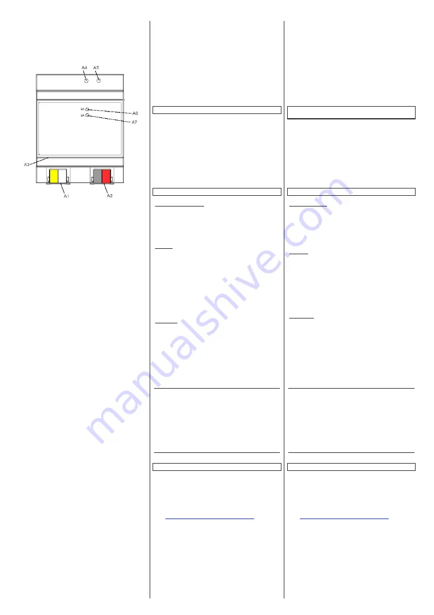
Lage- und Funktion der Anzeige- und Bedienelemente
A1 AC/DC 24 V Busklemme (gelb-weiß)
A2 EIB Busklemme (schwarz-weiß)
A3 Ethernet RJ45 Stecker
A4 EIB Programmier LED
A5 EIB Lerntaste
A6 Ethernet Link LED
A7 Ethernet Activity LED
Die Geräteanschlüsse, sowie die bei der EIB-Inbetriebnahme
benötigten Elemente Lerntaste und Programmier-LED sind in
dem Verteiler nur bei entfernter Abdeckung zugänglich.
Montage und Verdrahtung
Allgemeine Beschreibung
Das Reiheneinbaugerät kann in Niederspannungsverteilern
(Auf-Putz oder Unter-Putz) und überall dort eingesetzt werden,
wo Hutschienen nach EN 60715-TH35-7,5 vorhanden sind.
Die Verbindung mit der Buslinie erfolgt über eine Busklemme.
Zur Verbindung mit dem Ethernet-IP Datennetzwerk verfügt das
Gerät über eine RJ45 Buchse.
Montage
−
Schnappen Sie den IP Viewer N151 auf die Hutschiene auf.
−
Verbinden Sie die Hilfsspannung AC/DC 24V mit der gelb-
weißen Busklemme (A1).
−
Verbinden Sie die Busleitung mit der schwarz-roten Bus-
klemme (A2).
−
Stecken Sie ein Ethernet Patchkabel mit RJ45 Stecker in die
RJ45 Buchse (A3), um das Gerät mit dem LAN / Intranet zu
verbinden.
Es besteht eine Verbindung zu einem Netzwerk, wenn die
gelbe LED mit der Kennzeichnung LK (A6) dauernd leuchtet.
Wenn die LED LA (A7) aufleuchtet, werden Daten vom bzw.
zum Gerät gesendet.
Demontage
−
Entfernen Sie zuerst das Ethernet Patchkabel aus der RJ45
Buchse (A3).
−
Entfernen Sie die gelb-weiße Busklemme (A1) aus der Buch-
se.
−
Entfernen Sie die schwarz-rote Busklemme (A2) aus der
Buchse.
−
Lösen Sie den Schnapper und heben das Gerät von der Hut-
schiene.
V
WARNUNG
•
Das Gerät darf nur von einer zugelassenen Elektrofachkraft
installiert und in Betrieb genommen werden.
•
Freie Hutschienenbereiche mit eingelegter Datenschiene sind
mit der Abdeckung 5WG1 192-8AA01
abzudecken.
•
Die geltenden Sicherheits- und Unfallverhütungsvorschriften
sind zu beachten.
•
Das Gerät darf nicht geöffnet werden.
•
Bei der Planung und Errichtung von elektrischen Anlagen
sind die einschlägigen Richtlinien, Vorschriften und Bestim-
mungen des jeweiligen Landes zu beachten.
Allgemeine Hinweise
•
Die Bedienungsanleitung ist dem Kunden auszuhändigen.
•
Ein defektes Gerät ist an die zuständige Geschäftsstelle der
Siemens AG zu senden.
•
Bei zusätzlichen Fragen zum Produkt wenden Sie sich bitte
an unseren Technische Unterstützung:
!
+49 (180) 5050-222
!
+49 (180) 5050-223
"
www.siemens.de/automation/support-request
Seite 2 von 2
Mechanical specifications
•
Dimensions: DIN-rail mounted device,
Width 4SU (1 SU = 18 mm), height 55 mm
•
Fire load: approx. 3.300 kJ kJ ± 10 %
•
Weight: approx. 150 g
Electrical safety
•
Protection class (to EN 60529): IP 20
Environmental specifications
•
Climatic conditions: EN 50090-2-2
•
Ambient temperature in operation: 0 ... + 45
°
C
•
Storage temperature: - 25 ... + 70
°
C
•
Relative humidity (non-condensing): 5% to 93%
Location and Function of the Display and Operating Ele-
ments
A1 AC/DC 24V bus connector terminal (yellow-white)
A2 EIB bus connector terminal (black-red)l
A3 Ethernet RJ45 socket
A4 EIB programming LED
A5 EIB learning button
A6 Ethernet link LED
A7 Ethernet activity LED
The device connections and the elements needed for EIB com-
missioning - learning button and programming LED - are acces-
sible in the distribution board only when the lid is removed.
Mounting and Wiring
General description
The N-system DIN-rail device can be installed in distribution
boards, surface or flush mounted, or on any DIN rail complying
with EN 60715-TH35-7,5.
The connection to the bus line is established via the bus connec-
tor terminal (red-black) on the top side.
The RJ45 socket on the device front side provides the connec-
tion to the Ethernet-IP data network.
Mounting
−
Snap the IP Viewer N151 on to the DIN rail.
−
Connect the auxiliary power AC/DC 24V with the yellow-
white bus connector terminal (A1).
−
Connect the bus line with the black-red bus connector termi-
nal (A2).
−
Plug an Ethernet patch cable with an RJ45 plug into the
RJ45 socket (A3) to connect the device with the LAN/Intranet.
A connection is established to the network when the yellow
LED marked LK (A6) is continuously lit. When the LED LA (A7)
flashes data is sent to or from the device.
−
Dismounting
−
Unplug the Ethernet patch cable from the RJ45 socket (A3)
−
Remove the yellow-white bus connector terminal (A1) from
its socket.
−
Remove the black-red bus connector terminal (A2) from its
socket.
−
Remove the device from the DIN rail
V
WARNING
•
The device may only be mounted and commissioned by an
authorised electrician.
•
Exposed sections of DIN rail with integrated data rails are to
be covered with the lid 5WG1 192-8AA01.
•
The relevant safety and accident prevention rules are to be
obeyed.
•
The device must not be opened.
•
When planning and construction of electrical installations,
the relevant national guidelines, rules and regulations of the
country in question are to be obeyed.
General notes
•
The operating instructions must be handed to the client.
•
Any faulty device should be returned to the local Siemens of-
fice.
•
If you have further questions concerning the product, please
contact our Technical Support:
!
+49 (180) 5050-222
!
+49 (180) 5050-223
"
www.siemens.de/automation/support-request
Page 2 of 2
A5E01251112B
DS01


