background image

2

IMPORTANT

The information contained herein is general in nature and is not intended for
specific application purposes nor is it intended as a training manual for
unqualified personnel. Refer to Note for definition of a 

qualified person

.

It does not relieve the user of responsibility to use sound practices in
application, installation, operation and maintenance of the equipment
purchased or in personnel safety precautions. Should a conflict arise
between the general information contained in this publication and the
contents of drawings or supplementary material or both, the latter shall take
precedence. Siemens Energy & Automation, Inc. reserves the right to make
changes in specifications shown herein or add improvements at any time
without notice or obligation.

NOTE

*Authorized and qualified personnel—

For the purpose of this manual a qualified person is one who is familiar with
the installation, construction or operation of the equipment and the hazards
involved. In addition, he has the following qualifications:
(a)

is trained and authorized

 to de-energize, clear, ground, and tag

circuits and equipment in accordance with established safety prac-
tices.

(b)

is trained

 in the proper care and use of protective equipment such as

rubber gloves, hard hat, safety glasses or face shields, flash clothing,
etc., in accordance with established safety practices.

(c)

is trained

 in rendering first aid.

SUMMARY

These instructions do not purport to cover all details or variations in
equipment, nor to provide for every possible contingency to be met in
connection with installation, operation, or maintenance. Should further
information be desired or should particular problems arise which are not
covered sufficiently for the purchaser’s purposes, the matter should be
referred to the local sales office, listed on back of this instruction guide.

The contents of this instruction manual shall not become part of or modify
any prior or existing agreement, commitment or relationship. The sales
contract contains the entire obligation of Siemens Energy & Automation,
Inc. The warranty contained in the contract between the parties is the sole
warranty of Siemens Energy & Automation, Inc. Any statements contained
herein do not create new warranties or modify the existing warranty.

Содержание I-T-E Sensitrip MD Series

Страница 1: ...Bulletin SIB2 7 8 Sensitrip MD ND Frame Information and Instruction Guide I T E Molded Case Circuit Breakers ...

Страница 2: ......

Страница 3: ...29 Mechanical Interlock 30 33 Accessories Shunt Trip Undervoltage Trip Auxiliary Switch and Bell Alarm Switch Installation 34 35 Accessories Cont d Shunt Trip and Undervoltage Trip Mechanical and Electrical Check 36 Auxiliary Switch and Bell Alarm Switch Mechanical and Electrical Check 37 Rotary Handle 38 39 Max Flex Flange Mount Handle Operator 40 44 TELEMAND Electric Motor Operator 45 47 Connect...

Страница 4: ...trained and authorized to de energize clear ground and tag circuits and equipment in accordance with established safety prac tices b is trained in the proper care and use of protective equipment such as rubber gloves hard hat safety glasses or face shields flash clothing etc in accordance with established safety practices c is trained in rendering first aid SUMMARY These instructions do not purpor...

Страница 5: ...uit breakers AAAA AAAA AAAA AAAA AAAA AAAA AAAA AAAA AAAA AAAA AAAA AAAA AAAA AAAA AAAA AAAA AAAA AAAA AA AA AAAA AAAA AAAA A A A AAAA AAAA AAAA AAAA AAAA AAAA AAAA AAAA AAAA Adjustments Breaker Suffix Letters A AG ANT ANGT Long Time Adj Current Setting Adj Long Time Delay Adj Instantaneous Setting Adj Short Time Pick Up Adj Short Time Delay Adj Short Time I t Pick Up Adj Ground Fault Pick Up Adj ...

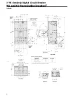
Страница 6: ...4 I T E Sensitrip Digital Circuit Breaker MD and ND Frame Outline Drawings 1 3 Pole ...

Страница 7: ...e ments Inspect the device for completeness and check for any damage before mounting C Device must be in TRIPPED or OFF position prior to mounting D To mount the device perform the following steps 1 For individual enclosures panelboards and switch boards manufactured by Siemens Energy Auto mation Inc follow the instructions provided with this equipment 2 For those applications where mounting is on...

Страница 8: ...6 MD and ND Frame Trip Adjustments ...

Страница 9: ...x times the continuous amps setting 1 See Figure 1 for the possible settings for this switch Ig Ground Fault Pickup a function of adjustment setting expressed in of In Adjustable Continuous Amps Switch Ir In All SMD SND solid state molded case circuit breakers have an adjustable continuous amps rating switch Adjustments made to this switch can change the continuous amps rating of the breaker to 20...

Страница 10: ...sition disables the function See Figure 1 for the possible settings for this switch Ig Ground Fault Pickup a function of adjustment setting expressed in of In Adjustable Short Time Delay Seconds SMD SND models with an adjustable short time delay switch allow for selection from two modes of short time delays The first range of settings enable the breaker to be set for fixed time delays of 05 1 2 3 ...

Страница 11: ...nstantaneous setting on MAX time delay is eliminated Ig Ground Fault Pickup a function of adjustment setting expressed in of In Adjustable Ground Fault Pickup Pickup Ig In Delay 12 t 51n Ground fault protection is available for 3 phase 3 wire and 3 phase 4 wire neutral electrical systems SMD SND models with an adjustable ground fault delay switch allow for the selection of ground fault pickup at 2...

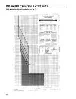
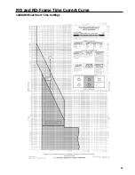
Страница 12: ...10 MD and ND Frame Time Current Curve 600 1000A With Short Time Delay Set on Fixed Time ...

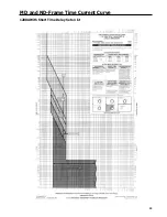
Страница 13: ...MD and ND Frame Time Current Curve 11 1200A With Short Time Delay Set on Fixed Time ...

Страница 14: ...12 MD and ND Frame Time Current Curve 600 100A With Short Time Delay Set on I2 t ...

Страница 15: ...MD and ND Frame Time Current Curve 13 1200A With Short Time Delay Set on I2 t ...

Страница 16: ...14 MD and ND Frame Time Current Curve 600 100A Without Short Time Settings ...

Страница 17: ...MD and ND Frame Time Current Curve 15 1200A Without Short Time Settings ...

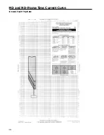
Страница 18: ...16 MD and ND Frame Time Current Curve Ground Fault Trip Data ...

Страница 19: ...MD and ND Frame Time Current Curve 17 Example ...

Страница 20: ...18 MD and ND Frame Let Thru Curves ...

Страница 21: ...eaker Mounting Preparation A Turn off and lock out all power supplying circuit breaker before installing B Drill mounting panel as shown in drilling plan Figure 1 This user provided panel must be made from a material acceptable for supporting uninsulated live parts and have adequate strength to support the circuit breaker Thickness should be 1 4 in min and 1 in max C Figures 1 and 2 show dimension...

Страница 22: ... the breaker Figure 4 F Replace the breaker terminal shields 1 on the line and load side of the circuit breaker and secure with four breaker terminal shield screws 2 Tighten to 12 in lb G Affix label this device is equipped with rear connecting studs 8J to the front of the circuit breaker Figure 3 H If installation requires use of front panel trim provide cutout for breaker escutcheon Figure 5 Ins...

Страница 23: ...screws flatwashers and lockwashers 4 Figure 4 Torque each screw to 72 in lb H Insert the end shields 7 into the slots provided at the line and load ends of the breaker Figure 4 I Replace the breaker terminal shields 1 on the line and load side of the circuit breaker and secure with four breaker terminal shield screws 2 Tighten to 12 in lb Figure 3 J Affix label 8 This device is equipped with rear ...

Страница 24: ...nded torque is 228 in Ib NOTE Steps C and D may be completed in any convenient order E Attach power cables to connectors and tighten set screws 5 Figure 1 to specifications per Table 1 NOTE Cables must extend straight for at least 4 inches from face of connector to clear shield F Mount removable terminal shield 6 Figure 2 to end of circuit breaker Shield should be flush with end of circuit breaker...

Страница 25: ... or 2 pcs 1 AWG 500 MCM Cu AI 375 in lb MD6 SMD6 HMD6 SHMD6 CMD6 SCMD6 ND6 SND6 HND6 SHND6 CND6 SCND6 TA3K500 500 800 1 thru 3 pcs 1 0 500 MCM Cu AI 375 in lb TA4P8500 800 1200 1 thru 4 pcs 250 500 MCM Cu AI 375 in lb TC2K500 500 800 1 or 2pcs 1 AWG 500 MCM Cu 375 in lb TC3K350 500 800 1 thru 3 pcs 1 AWG 350 MCM Cu 375 in lb TA2K8750 500 800 1 or 2 pcs 500 750 MCM Cu AI 375 in lb TA2K8750 500 1200...

Страница 26: ...ghly with a wire brush or other suitable means to remove oxides and other contaminants from the conductor NOTE Copper wires and the compression connector should not be cleaned abrasively F Remove cap from compression connector and insert cable fully into barrel 1 Figure 1 of connector G Insure that connector tang s 2 Figure 1 are in their proper orientation prior to crimping This helps avoid twist...

Страница 27: ...ical spring washer Conical spring washer is to be installed with convex side of washer toward underside of screw head Figure 4 Torque screw to 228 in lb NOTE When using this kit for ampacities less than 1200A or where only one or two connectors are to be mounted to the terminal pad insert spacers provided in kit between spring washer and compression lug Figures 4a 4b 4c and 4d Figure 4 ...

Страница 28: ... Figure 1 Figure 1 D With a screwdriver turn the screws so they enter the blind holes molded in each side of the toggle handle Tighten the two screws evenly so that when they engage the bottom of the blind holes they project an equal distance of 094 in Figure 2 above the tapped surface Do not over torque Maximum torque 2 in Ib Figure 2 Modification and Use for Blocking the Handle ON The lip of the...

Страница 29: ...Figure 1 Figure 1 D With a screwdriver turn the screws so they enter the blind holes molded in each side of the toggle handle Tighten the two screws evenly so that when they engage the bottom of the blind holes they project an equal distance of 094 in Figure 2 above the tapped surface Do not over torque Maximum torque 2 in Ib Figure 2 Installation of Handle Padlocking Device To install the padlock...

Страница 30: ...hers 4 and 3 8 16 in hex nuts 5 furnished Tighten to 216 in lb Breaker Preparation Figure 4 A Loosen four breaker terminal shield screws 6 and remove both line and load side terminal shields 7 Caution Make certain that breaker operating handle is in OFF position before proceeding with the next step Remove pressure wire connectors from breaker if present B Place tulip clip assembly 8 on back of bre...

Страница 31: ...Installation Diagrams 29 ...

Страница 32: ...cover s or device and while cover s are removed B Remove terminal shield 1 from line and load side of breaker frame Two 8 32 screws each Figure 1 C Remove load cover 2 from breaker frame Six 10 32 x 3 4 screws and two 10 32 x 13 8 in screws Figure 1 D Remove from left pole only the two socket head cap screws and the two belleville spring washers and dis card ...

Страница 33: ...d Select proper length of plunger 11 Figures 2 and 3 for desired application and discard the pair of plungers not used Position support tie bar assembly from top and insert plunger through rectangular opening in base from bottom of base Tie bar member 12 must fit around tie bar connec tor Figure 3 It may be necessary to gently tap tie bar member down to achieve snug fit Position of Link Assembly C...

Страница 34: ...in into hole in rocker arm pin and secure by spreading ends Figure 7 D Add circuit breakers specially prepared to customer s panel for panel mounted or plug in adapters and circuit breakers for plug in applications Refer to installation instructionsuppliedwithplug inadaptersCatalogPC5662 or PC5663 Carefully position circuit breaker over 1 00 in diameter hole in panel so as not to damage protruding...

Страница 35: ...I T E Mechanical Interlock M15404 33 Figure 7 ...

Страница 36: ...ld always exit accessory toward outer edge of breaker Feed accessory leads down and through 670 x 300 in elongated opening 7 Figure 2 to bring leads out bottom of circuit breaker Figure 2 B Pull gently and evenly on accessory wire leads 2 to 9 wires while lowering accessory onto base Make sure all the slack is removed from leads inside breaker Accessory is placed in circuit breaker on nosepiece 8 ...

Страница 37: ...eaker Attach internal acces sory ID label 16 Figure 4 to top of circuit breaker on right hand side Make sure it is located in the proper space on existing label Attach wiring label 17 on side of circuit breaker cover as shown NOTE This accessory is suitable to use for Ground Fault Protection when combined with Class I Ground Fault Sensing Element equipped with internal clearing switch Figure 4 ...

Страница 38: ...01MN6 S02MN6 S03MN6 S15MN6 S04MN6 S06MN6 DC 12 24 48 125 250 2 15 0 98 2 16 0 89 1 77 S16MN6 S07MN6 S09MN6 S11MN6 S13MN6 Undervoltage Trip A With breaker in TRIPPED position connect test circuit to accessory leads Energize undervoltage trip device at 85 percent of the marked rated voltage of the coil Reset and turn breaker handle ON B Reduce voltage to 35 percent of rated coil voltage Circuit brea...

Страница 39: ...talog Number Number of Auxiliary Switches Ampere Rating of Switch Volts AC Volts DC 120 240 480 125 250 B00MN64 A01MN64B A02MN64B A01MN64 A02MN64 0 1 2 1 2 10 10 10 10 10 10 10 10 10 10 10 10 10 10 10 5 5 5 5 5 25 25 25 25 25 BellAlarmWireIdentification AllWithThreeLeads AAAA AAAA AAAA AAAA AAA AAA AAA AAA AAAA AAAA AAAA AAAA A A A A AAAA AAAA AAAA AAAA AAAA AAAA AAAA AAAA AAAA AAAA AAAA AAAA AAAA...

Страница 40: ...f the circuit breaker cover located above the circuit breaker handle Figure 4 D Position the breaker operator 7 on the circuit breaker and attach at the top using the two 10 32 x 1 00 pan head screws 8 and lock washers Torque these screws to 25 in Ib Attach the breaker operator at the bottom using the four 10 14 x 500 Phillips head thread forming screws 9 Torque to 20 in Ib maximum Figure 4 NOTE T...

Страница 41: ...Installation Diagrams 39 ...

Страница 42: ...operator on the flange section of the enclosure Application The Max Flex Operator is designed to work with l T E circuit breakers having current ratings through 1200 amperes The Max Flex unit meets all the industrial criteria such as UL and Automotive Industry Standards Design The new Max Flex Handle Operator provides maximum flex ibility in design and assembly of electrical equipment The cable de...

Страница 43: ...sions AAAA AAAA AAAA AA AA AA AAAA AAAA AAAA AAAA AAAA AAAA AAAA AAAA AAAA AAAA AAAA AAAA A A AAAA AAAA AAA AAA AAAA AAAA AA AA AAAA AAAA AAA AAA AAAA AAAA AAA AAA Enclosur Depth 48 Cable 60 Cable Up Down Up Down 10 8 21 5 17 5 31 5 12 7 5 21 18 32 5 16 6 5 21 19 32 18 6 20 5 18 5 32 20 6 20 16 5 31 5 24 4 19 14 31 30 1 5 15 5 11 28 5 36 6 5 23 5 Table 2 shows the maximum horizontal distance that ...

Страница 44: ...e When the enclosure door is closed the door latch mechanism automatically defeats the interlock F If no door catch is provided with the enclosure attach the door catch bracket and adjustable door catch to the enclosure door Door Catch Adjustment A Close the enclosure door and move the handle into the ON position If the handle cannot be moved from the ON position adjust the door catch downward in ...

Страница 45: ...sing 10 32 x 3 8 in screws and lockwashers Tighten to 75 in Ib NOTE Detent in cable retainer 17 must align with groove 18 in metal fitting of cable Figure 6 Tighten Detent Screws C Prior to attaching output end of cable to handle frame confirm that supply power to the circuit breaker has been turned off D Move circuit breaker handle to the ON position E Slide the threaded cable rod 19 through the ...

Страница 46: ...rip the circuit breaker by pushing the PUSH TO TRIP button C Check that the circuit breaker resets by moving the operating handle from ON to OFF and back to ON If the breaker resets tighten the spring adjuster one additional turn Attach lockwashers and 1 4 28 nut to the end of the cable rod and tighten to 32 in Ib D If the circuit breaker does not reset tighten the spring adjusters one turn and re...

Страница 47: ...r more details Operator Selection AAAA AAAA AAAA AAAA AAAA AAAA AAAA AAAA AAAA AAAA AAAA AAAA AAA AAA AAA AAA AAAA AAAA AAAA AAAA AAAA AAAA AAAA AAAA AAAA AAAA AAAA AAAA AAAA AAAA AAAA AAAA Motor Operator Frame For Use With I T E Circuit Breakers and Switch Types MOMN6120 MOMN6120L MOMN6240 MOMN6240L MD ND MD6 HMD6 CMD6 SMD6 SHMD6 SCMD6 ND6 HND6 CND6 SND6 SHND6 SCND6 MD6 ETI CMD6 ETI Installation ...

Страница 48: ...breakerhandlereaches the OFF position the motor circuit is disconnected by an internal limit switch When the circuit breaker trips automatically there is no external indication that the breaker has tripped unless a separate Bell Alarm accessory contact Siemens for appropri ate catalog number is provided to energize a customer furnished warning device After the circuit breaker trips auto matically ...

Страница 49: ...Installation Diagrams 47 ...

Страница 50: ...48 I T E Panelboard Connecting Straps 1 ...

Страница 51: ...service entrance equipment Type 12 MND612 A special industry sheet steel enclosure for indoor use in atmosphere containing particles of lint dust dirt sawdust and other foreign matter Type 3R MND63 Anoutdoor sheet steelenclosureprovidingprotectionagainst driving rain sleet or snow Listed as service entrance equip ment ...

Страница 52: ...ndle 1 4 turn clockwise looking from inside the enclosure door and attach the latch plate roller to the handle shaft while inserting the bent leg of the spring into the hole in the latch plate Fasten with a locking type flange nut Tighten the nut then loosen l 8 turn to allow movement of the roller assemblies Figure 1 NOTE Straight leg of spring must rest against pin 12 on handle plate See inset o...

Страница 53: ...Installation Diagrams 51 ...

Страница 54: ...Ampere Rating In Catalog Numbers 600 N06SMDA 700 N07SMDA 800 N08SMDA 1000 N10SNDA 1200 N12SNDA Caution The ampere rating of the transformer must be the same as the circuit breaker Max Rating In for proper operation Failure to match neutral sensor ampere rating with breaker ampere rating may result in nuisance trip ping or no trip due to ground fault which could result in property damage Bus Bar Sy...

Страница 55: ...20 screws lockwashers and nuts 3 NOTE Mount screws 3 in direction shown Figure 3 to maintain electrical spacing E Connect leads from terminal X and X2 5 on the neutral sensing transformer 2 using the 10 32 terminal screws 6 provided Figure 3 NOTE DO NOT use these neutral transformers with the following circuit breakers N06SMDA with SMD69600G SMD69600NGT SHMD69600G SHMD69600NGT SCMD69600G SCMD69600...

Страница 56: ... will prompt for the Breaker switch settings The TS 31 will respond with Enter continuous current setting in Enter instantaneous pickup setting Enter long time delay in seconds For breakers with short time functions you may be asked one of the following Enter short time Pickup Select Short Time Delay 1 Fixed 2 12 t Enter short time delay in seconds Enter 12 t delay in seconds For breakers with gro...
Страница 57: ...results CT Resistance Test Phase X Passed Press ENTER to exit test and continue CT Resistance Test Phase X Failed Press ENTER to exit test and continue CT Resistance Test Phase X Open Press ENTER to exit test and continue CT Resistance Test Phase X Short Press ENTER to exit test and continue The Phase X Failed message indicates that the CT resistance is neither open nor shorted but is not within d...

Страница 58: ...5 25 SMD69600AG SMD69700AG SMD69800AG 600 700 800 65 65 65 50 50 50 25 25 25 SMD69600ANT SMD69700ANT SMD69800ANT 600 700 800 65 65 65 50 50 50 25 25 25 SMD69600ANGT SMD69700ANGT SMD69800ANGT 600 700 800 65 65 65 50 50 50 25 25 25 SHMD6 3 Pole 600V AC SHMD69600A SHMD69700A SHMD69800A 600 700 800 100 100 100 65 65 65 50 50 50 SHMD69600AG SHMD69700AG SHMD69800AG 600 700 800 100 100 100 65 65 65 50 50...

Страница 59: ...0AG 800 1000 1200 65 65 65 50 50 50 25 25 25 SND69800ANT SND691000ANT SND691200ANT 800 1000 1200 65 65 65 50 50 50 25 25 25 SND69800ANGT SND691000ANGT SND691200ANGT 800 1000 1200 65 65 65 50 50 50 25 25 25 SHND6 3 Pole 600V AC SHND69800A SHND691000A SHND691200A 800 1000 1200 100 100 100 65 65 65 50 50 50 SHND69800AG SHND691000AG SHND691200AG 800 1000 1200 100 100 100 65 65 65 50 50 50 SHND69800ANT...

Страница 60: ...U01MN64AA U02MN64AA U03MN64AA U15MN64AA U04MN64AA N A 24 48 125 250 U07MN6 U09MN6 U11MN6 U13MN6 U07MN64A U09MN64A U11MN64A U13MN64A U07MN64AA U09MN64AA U11MN64AA U13MN64AA Auxiliary Switch AAAA AAAA AAAA AAAA AAAA AAAA AAAA AAAA AAAA AAAA AAAA AAAA AAAA AAAA AAAA AAAA AAA AAA AAAA AAAA AAAA AAAA AAAA AAAA AAAA AAAA AAA AAA AAAA AAAA AAAA AAAA AAAA AAAA AAAA AAAA AAAA AAAA AAAA AAAA A A A AAAA AAAA...

Страница 61: ...or RHONBO Standard Length Shaft RHONSSD 1 Each kit consists of 2 connectors or 3 connectors plus NDTS end barrier Item Catalog No Handle Operators continued Rotary Variable Depth Complete Mechanism RHONVD Handle Only 1 RHOH Breaker Operator RHONBO Variable Length Shaft RHONSVD Max FlexTM Flange Mounted Complete Mechanism FHONO48 Handle Only 2 FHOHN Breaker Operator FHONBO Cable Assembly 3 FHONCO48...

Страница 62: ... TA4P500 4 250 500 MCM Cu AI 375 in Ib CCMB00 See instructions For the correct 90 C wire size use Table 8 1 in UL 489 according to the rating of the breaker National Fire Protection Assoc National Electrical Code Federal Specification C 375B GEN Underwriters Laboratories Inc UL 489 Canadian Standards Association C22 2 No 5 ND Frame ND Frame breaker types are suitable for continuous opera tion at 1...

Страница 63: ...Siemens Energy Automation Inc 3333 State Bridge Rd Alpharetta GA 30201 Bulletin SIB2 7 8 New c 1990 Siemens Energy Automation Inc ...

Отзывы: