3 0
I-T-E Mechanical Interlock (M15404)
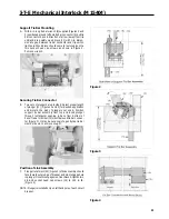
Figure 1
Circuit Breaker Preparation
A.
Turn off and lock out all power supplying circuit breaker
or frame before removing cover(s) or device and while
cover(s) are removed.
B.
Remove terminal shield (1 ) from line and load side of
breaker frame. Two #8-32 screws each (Figure 1).
C.
Remove load cover (2) from breaker frame. Six #10-32
x 3/4 screws and two #10-32 x 13/8 in. screws (Figure
1).
D.
Remove from left pole only, the two socket head cap
screws and the two belleville spring washers and dis-
card.
Содержание I-T-E Sensitrip MD Series
Страница 2: ......
Страница 6: ...4 I T E Sensitrip Digital Circuit Breaker MD and ND Frame Outline Drawings 1 3 Pole ...
Страница 8: ...6 MD and ND Frame Trip Adjustments ...
Страница 12: ...10 MD and ND Frame Time Current Curve 600 1000A With Short Time Delay Set on Fixed Time ...
Страница 13: ...MD and ND Frame Time Current Curve 11 1200A With Short Time Delay Set on Fixed Time ...
Страница 14: ...12 MD and ND Frame Time Current Curve 600 100A With Short Time Delay Set on I2 t ...
Страница 15: ...MD and ND Frame Time Current Curve 13 1200A With Short Time Delay Set on I2 t ...
Страница 16: ...14 MD and ND Frame Time Current Curve 600 100A Without Short Time Settings ...
Страница 17: ...MD and ND Frame Time Current Curve 15 1200A Without Short Time Settings ...
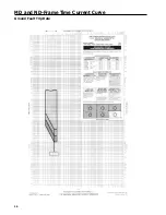
Страница 18: ...16 MD and ND Frame Time Current Curve Ground Fault Trip Data ...
Страница 19: ...MD and ND Frame Time Current Curve 17 Example ...
Страница 20: ...18 MD and ND Frame Let Thru Curves ...
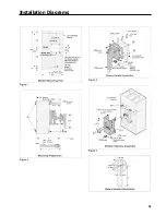
Страница 31: ...Installation Diagrams 29 ...
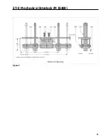
Страница 35: ...I T E Mechanical Interlock M15404 33 Figure 7 ...
Страница 41: ...Installation Diagrams 39 ...
Страница 49: ...Installation Diagrams 47 ...
Страница 50: ...48 I T E Panelboard Connecting Straps 1 ...
Страница 53: ...Installation Diagrams 51 ...

