Parameter reference
8.6 Setup (2.)
HydroRanger 200 HMI
216
Operating Instructions, 06/2018, A5E36281317-AC
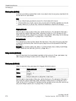
Flush system (2.10.3.)
Controls an electrically operated flush valve on a pump to divert some pump output back into
the wet well to stir up sediment.
Note
•
If any of the following parameters are set to 0, this feature will not work.
•
In Dual-point mode, a flush valve can be set up for each of the three available level inputs
[Sensor Mode (2.1.3.) (Page 163) = Dual-Point Difference or Dual-Point Average].
Single-point mode
Enter the device relay number of the pump with the flush valve. The activation of this pump
relay drives the usage of the flush system. Both Flush Cycles (2.10.3.3.) (Page 217) and
Flush Interval (2.10.3.4.) (Page 217) are based on the operation of this relay, and control any
relay set to Relay Function (2.8.1.4.) (Page 195) = Flush Valve.
Dual-point mode
The indexed relay is the one that controls the flush device. The value is the pump relay that
is watched by the flush system. Enter the pump relay value into the parameter at the flush
relay index.
Example: If you need to watch pump Relay 1 to control a flush valve on Relay 2 (with Relay
index 2 selected), set Flush Pump (2.10.3.2.) (Page 216) = 1.
Relay selector (2.10.3.1.)
Sets the relay index for all parameters applicable to this sub-menu. These parameters only
affect relays set to Relay Function (2.8.1.4.) (Page 195) = Flush Valve.
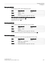
Flush pump (2.10.3.2.)
Picks the number of the pump relay which triggers the flushing device.
Index
Single-point model
Dual-point model
Global
Relay
Values
Range: 0 ... 6
Preset: 0
Related
Relay Function (2.8.1.4.) (Page 195) = Flush Valve
Enter the device relay number of the pump with the flush valve. The activation of this pump
relay drives the usage of the flush system. Both Flush Interval (2.10.3.4.) (Page 217) and
Flush Cycles (2.10.3.3.) (Page 217) are based on the operation of this relay and controls any
relay set to Relay Function (2.8.1.4.) (Page 195) = Flush Valve.
Содержание HydroRanger 200 HMI
Страница 2: ......
Страница 20: ...Introduction 1 5 Notes on warranty HydroRanger 200 HMI 18 Operating Instructions 06 2018 A5E36281317 AC ...
Страница 24: ...Safety notes HydroRanger 200 HMI 22 Operating Instructions 06 2018 A5E36281317 AC ...
Страница 28: ...Description 3 5 Modbus communication HydroRanger 200 HMI 26 Operating Instructions 06 2018 A5E36281317 AC ...
Страница 159: ...Parameter reference 8 2 Parameter indexing HydroRanger 200 HMI Operating Instructions 06 2018 A5E36281317 AC 157 ...
Страница 276: ...Parameter reference 8 10 Language 6 HydroRanger 200 HMI 274 Operating Instructions 06 2018 A5E36281317 AC ...
Страница 322: ...Pump control reference B 13 Other pump controls HydroRanger 200 HMI 320 Operating Instructions 06 2018 A5E36281317 AC ...
Страница 352: ...Communications C 41 Single parameter access SPA HydroRanger 200 HMI 350 Operating Instructions 06 2018 A5E36281317 AC ...
Страница 354: ...Updating software HydroRanger 200 HMI 352 Operating Instructions 06 2018 A5E36281317 AC ...
Страница 359: ...HydroRanger 200 HMI Operating Instructions 06 2018 A5E36281317 AC 357 Conduit entry for Class I Div 2 applications F ...
Страница 360: ...Conduit entry for Class I Div 2 applications HydroRanger 200 HMI 358 Operating Instructions 06 2018 A5E36281317 AC ...
Страница 361: ...Conduit entry for Class I Div 2 applications HydroRanger 200 HMI Operating Instructions 06 2018 A5E36281317 AC 359 ...
Страница 362: ......
Страница 372: ...Programming chart G 1 Programming chart HydroRanger 200 HMI 370 Operating Instructions 06 2018 A5E36281317 AC ...
Страница 390: ...LCD menu structure H 1 LCD Menu Structure HydroRanger 200 HMI 388 Operating Instructions 06 2018 A5E36281317 AC ...
Страница 403: ......


