


Operating
7.3 Relays
HydroRanger 200 HMI
98
Operating Instructions, 06/2018, A5E36281317-AC
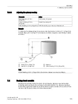
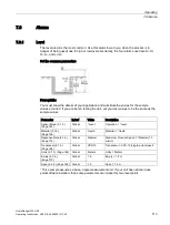
7.3.7
Relay-related parameters
Some parameters affect how relays react during normal conditions:
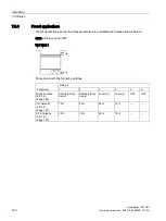
Setpoint
When a setpoint is reached, the corresponding action is taken. The setpoint can
be an ON or OFF setpoint related to a process variable.
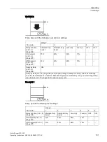
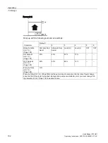
ON and OFF
setpoints
Sets the process point at which the relay is activated (ON setpoint) then reset
(OFF setpoint). These setpoints are set separately for each pump within each
pump control, and for each alarm type.
(Page 194)
Sets the device to a preset application. These preset applications quickly set up
the device with a minimum number of parameters.
(Page 195)
Sets the default state differently, depending on whether the relay is programmed
as an alarm or a control. The alarm function de-energizes the relay coils. During
normal operation (no alarms), the relay coils are energized. The control function
energizes the relay coils. When the instrument is at rest (no controls operating)
the relay coils are de-energized.
(Page 197)
Sets the process point at which the relay is activated.
(Page 197)
Sets the process point at which the relay is de-activated.
(Page 199)
Affects relay reaction. Reverses the logic (normally-open to normally-closed or
vice versa).
(Page 201)
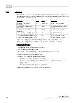
Changes how individual relays react to a fail-safe condition on the instrument.
Relay wiring test Relay Logic
(Page 255)
Checks the application wiring by forcing a relay control function,
such as a level alarm or pump control setpoint. Ensure all the
relay programming and wiring works properly.
Verify that ON and OFF respond correctly. Use this parameter
as a final test once all of the relay programming is done.
Содержание HydroRanger 200 HMI
Страница 2: ......
Страница 20: ...Introduction 1 5 Notes on warranty HydroRanger 200 HMI 18 Operating Instructions 06 2018 A5E36281317 AC ...
Страница 24: ...Safety notes HydroRanger 200 HMI 22 Operating Instructions 06 2018 A5E36281317 AC ...
Страница 28: ...Description 3 5 Modbus communication HydroRanger 200 HMI 26 Operating Instructions 06 2018 A5E36281317 AC ...
Страница 159: ...Parameter reference 8 2 Parameter indexing HydroRanger 200 HMI Operating Instructions 06 2018 A5E36281317 AC 157 ...
Страница 276: ...Parameter reference 8 10 Language 6 HydroRanger 200 HMI 274 Operating Instructions 06 2018 A5E36281317 AC ...
Страница 322: ...Pump control reference B 13 Other pump controls HydroRanger 200 HMI 320 Operating Instructions 06 2018 A5E36281317 AC ...
Страница 352: ...Communications C 41 Single parameter access SPA HydroRanger 200 HMI 350 Operating Instructions 06 2018 A5E36281317 AC ...
Страница 354: ...Updating software HydroRanger 200 HMI 352 Operating Instructions 06 2018 A5E36281317 AC ...
Страница 359: ...HydroRanger 200 HMI Operating Instructions 06 2018 A5E36281317 AC 357 Conduit entry for Class I Div 2 applications F ...
Страница 360: ...Conduit entry for Class I Div 2 applications HydroRanger 200 HMI 358 Operating Instructions 06 2018 A5E36281317 AC ...
Страница 361: ...Conduit entry for Class I Div 2 applications HydroRanger 200 HMI Operating Instructions 06 2018 A5E36281317 AC 359 ...
Страница 362: ......
Страница 372: ...Programming chart G 1 Programming chart HydroRanger 200 HMI 370 Operating Instructions 06 2018 A5E36281317 AC ...
Страница 390: ...LCD menu structure H 1 LCD Menu Structure HydroRanger 200 HMI 388 Operating Instructions 06 2018 A5E36281317 AC ...
Страница 403: ......