


de
sv
fi
Diese Anleitung ist beim Antrieb oder in der Anla-
gendokumentation aufzubewahren!
Dieses Symbol weist auf Gefahren und Mas-
nahmen zum Schutz von Personen und Sachen hin:
•
Antriebe für AC 230 V dürfen nur durch autorisier-
tes Personal angeschlossen werden.
•
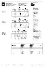
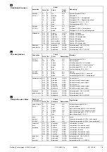
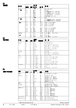
Zulässige Spannungen an den Hilfsschaltern:
Siehe Tabelle unter "Geräteschaltpläne".
•
Die Anschlusskabel des Antriebs dürfen nicht im
Wasser liegen.
Denna instruktion skall förvaras tillsammans med
ställdonet eller anläggningsdokumentationen!
Denna symbol gäller riskfaktorer samt åtgärder
för att undvika person- och materialskador.
•
Ställdon med AC 230 V får anslutas endast av
behörig personal.
•
Tillåten spänning för hjälpkontakter, se tabellen i
avsnitt kopplingscheman.
•
Ställdonets anslutningskabel får inte ligga i vatten.
Tätä ohjetta tulee säilyttää toimimoottorin lähei-
syydessä tai yhdessä laitosdokumenttien kanssa!
Tämä symboli viittaa vaaraan ja toimenpiteisiin,
joita tarvitaan henkilö- ja aineellisten vahinkojen vält-
tämiseksi:
•
Ainoastaan valtuutetut ammattihenkilöt saavat
liittää 230 VAC:n toimimoottoreita.
•
Sallitut jännitteet apukytkimissä: katso "Kytkentä-
kaaviot"-kappaleessa oleva taulukko.
•
Toimimoottorin liitäntäkaapelit eivät saa kastua tai
muuten altistua vedelle.
Gerät der Schutzklasse II (Schutzisolierung)
Apparat i isolerklass II (skyddsisolering)
Suojausluokan II laite (suoraerotus)
Gerät der Schutzklasse III (Schutzisolierung)
Apparat i isolerklass III (skyddsisolering)
Suojausluokan III laite (suojaerotus)
Achtung!
Der Stellantrieb darf nicht geöffnet
werden
OBS!
Ställdonet får inte öppnas.
Huomio!
Toimimoottoria ei saa avata.
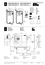
Voreinstellung
Werkseitig eingestellt: 5°.
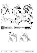
Handverstellung des Antriebes
Nur bei montiertem Stellungsanzeiger gemäss Ab-
schnitt C1 und C2 zulässig.
Verdrahtung und Inbetriebnahme
Siehe in den anlagenspezifischen Unterlagen und in
der Basisdokumentation "Technische Grundlagen"
CM2Z4634 zum Antrieb.
Förinställning
Fabriksinställning: 5°.
Manuell manövrering
Endast tillåten efter och lägesindikator enligt avsnitt
C1 och C2.
Elektrisk inkoppling och igångkörning
Se anläggningsspecifika underlag
och grund-
läggande beskrivning “Handbok CM2Z4634” för
ställdonet.
Akselin
Tehdasasetus: 5°.
Toimimoottorin käsiohjaus
Sallittua ainoastaan, ja asennonosoitin on asennettu
paikoilleen kohtien C1 ja C2 mukaisesti.
Johdotus ja käyttöönotto
Katso laitoskohtaiset dokumentit ja toimimoottorin
tekninen käsikirja CM2Z4634.
en
nl
es
Store these instructions together with the actua-
tor or with the plant documentation!
This symbol denotes dangers and measures to
avoid personal injury and property damage:
•
Only authorized personnel may connect actuators
for AC 230 V.
•
Refer to the table in "Diagrams" for the voltages
permissible at the auxiliary switches.
•
Do not expose the actuator's connecting cables to
water or lay the cables in water.
Deze handleiding moet bij de servomotor, of met
de documentatie van de installatie worden be-
waard!
Dit symbool wijst op gevaar en maatregelen ter
bescherming van personen en materiaal:
•
AC 230 V aandrijvingen mogen alleen door be-
voegd personeel worden aangesloten.
•
Voor toelaatbare spanningen aan hulpschakelaars:
Zie tabel onder "Aansluitschema‘s"
•
De aansluitkabel van de aandrijving mag niet in het
water liggen.
Conserve estas instrucciones con el actuador o
con la documentación de la instalación!
Este símbolo denota peligro y medidas para
evitar daños personales y de la propiedad:
•
Sólo el personal autorizado puede conectar los
actuadores a 230 V CA.
•
Consultar la tabla de "Conexionado eléctrico“ para
saber la tensión permitida en los contactos auxil-
iares
•
No exponer los cables de conexión del actuador al
agua ni dejarlos en contacto con ésta.
Device of protection class II (protective
insulation)
Apparaat van beschermingsklasse II (be-
schermings isolatie)
Equipo con tipo de protección II (aislamiento
protegido)
Device of protection class III (protective
insulation)
Apparaat van beschermingsklasse III (be-
schermings isolatie)
Equipo con tipo de protección III (ais-
lamiento protegido)
Warning!
Do not open the actuator.
Opgelet
! De servomotor mag niet worden
geopend.
Atención!
el actuador no debe ser abierto.
Presetting
Factory set: 5°.
Manual override of the actuator
Only allowed after position indicator, according to
section C1 and C2.
Wiring and commissioning
Refer to the actuator's commissioning instructions
and document "Technical basics" CM2Z4634.
Voorinstelling
Fabrieksmatig ingestelde: 5°
Handmatige verstelling van de servomotor
Alleen toegestann bij en standaanwijzers volgens
voorbeeld C1 en C2
Bekabeling en inbedrijfstelling
Raadpleeg de installatie-documentatie en de basis-
documentatie “technische grondslagen” CM2Z4634
van de servomotor.
Preajuste
Ajuste de fábrica: 5º.
Posicionamiento manual del actuador
Sólo debe accionarse después del eje y el indicador
de posición, según las secciones C1 y C2.
Cableado y puesta en marcha
Ver la documentación técnica “Technical basics”
CM2Z4634 del actuador.
fr
it
da
Cette instruction est à conserver avec le servo-
moteur ou avec la documentation de l’installation!
Ce symbole signale un danger pour les per-
sonnes et les biens et les mesures y-afférentes :
•
Le branchement des servomoteurs 230 V~ ne doit
être effectué que par un personnel qualifié.
•
Tensions admissibles sur les contacts auxiliaires :
cf. "Schémas de raccordement"
•
Les câbles de raccordement du servomoteur ne
doivent pas être en contact avec l'eau.
Queste istruzioni devono essere conservate con
la documentazione dell’impianto!
Questo simbolo indica – pericolo – il personale
deve fare attenzione per evitare ferite o danni.
•
I collegamenti a 230 V CA . devono sempre essere
eseguiti da personale autorizzati.
•
Fare riferimento alle “ tabelle tecniche“ per la ten-
sione ammessa per i contatti ausiliari.
•
Non esporre all‘acqua il cavo ed i collegamentii
elettrici.
Opbevar denne vejledning sammen med motoren
eller med anlægsdokumentationen!
Dette symbol gør opmærksom på farer og
forholdsregler til beskyttelse af personer og genstan-
de:
•
Motorer til AC 230 V må kun tilsluttes af autorisere-
de personer.
•
Tilladte spændinger til hjælpekontakter: Se skema
under "Apparatdiagrammer"
•
Motorens tilslutningskabler må ikke ligge i vand.
Classe d'isolation II (isolation de protection)
Apparecchi di protezione classe ii (protezi-
one isolamento)
Apparat i isoleringsklasse II (beskyttelsesi-
solering)
Classe d'isolation III (isolation de protection)
Apparecchio di protezione classe III (protezi-
one isolamento)
Apparat i isoleringsklasse III (beskyttelsesi-
solering)
Attention!
Le servo-moteur ne doit pas être
ouvert.
Attenzione!
Il servocomando non deve
essere aperto.
OBS!
Motoren må ikke åbnes.
Préreglage
Préreglé à l’usine: 5°.
Positionnement manuel du servo-moteur
Ne doit être actionné d’axe et de l’indicateur de posi-
tion, selon les sections C1 et C2.
Câblage et mise en service
se référer à la documentation de l’installation et au
manuel technique CM2Z4634 du servomoteur.
Collega Regolazione
Alla consegna: 5°.
Posizionamento manuale del servocomando
Può
essere azionato dopo il e dall’indicatore di posizione
secondo i paragrafi C1 e C2.
menti e messa in servizio
Consultare la documentazione per l’installazione e il
foglio tecnico (CM2Z4634) del servocomando.
Forindstilling
Fabriksindstillet: 5°.
Manuel justering af motor
Kun tilladt med monteret stillingsindikator i henhold til
afsnit C1 og C2.
Eltilslutning og idriftsættelse
Se den anlægsspecifikke dokumentation samt basis-
dokumentationen “Tekniske principper” CM2Z4634
for motoren.
2/8
02.11.2005
M4634
4 319 2883 0 g
Building Technologies / HVAC Products