


P/N 315-648952-7
PAGE 3 OF 4
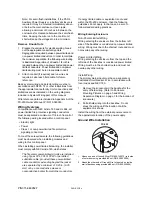
FS-250 Enclosure Mounting
BOX 18”
DOOR 18 3/8”
BOX 22”
DOOR 22 9/32”
11 9/64”
FS-250 ENCLOSURE
FS-250 ENCLOSURE WITH SEMI-FLUSH TRIM
11 9/64”
5 1/4”
Mount Control Unit
of convenient height
for access to
display and controls
Mount Control Unit
of convenient height
for access to
display and controls
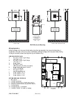
FS-250 ENCLOSURE
KNOCK OUT LOCATIONS
TOP AND BOTTOM OF
ENCLOSURE
1/2 AND 3/4 COMBINATION
KNOCKOUTS - 8 TOTAL
(7/8 AND 1 1/8 DIA.)
FS-250 BOX
1”
16”
20 7/16”
9/16” TYP.
25 1/8”
1 9/32”
2 5/8”
4 7/8”
13 1/8”
15 3/8”
18”
21 1/8”
3 1/2”
MAX
PRE-
ALARM
SILENCED
ALARM
ALARM
ON
AC POWER
SUPERVISORY
TROUBLE
SUPERVISORY
SILENCED
ALARM
PRE-
ALARM
ALARM
ON
AC POWER
TROUBLE
ACKNOWLEDGE
DE-ENERGIZE UNIT BEFORE SERVICING
7
CAUTION:
*
PORT
COM
1
GHI
4
PRS
ALARM SILENCE
M1
M2
C
8
9
0
#
D
MENU
SYSTEM RESET
ABC
2
3
JKL
TUV
5
6
WXY
MNO
DEF
A
B
M3
M4
ACKNOWLEDGE
DE-ENERGIZE UNIT BEFORE SERVICING
1
2
PORT
COM
7
*
GHI
4
PRS
8
0
JKL
TUV
5
CAUTION:
ALARM SILENCE
ABC
A
3
C
D
MENU
B
9
#
6
WXY
MNO
SYSTEM RESET
DEF
M1
M2
M3
M4
GND
N
AC
J1
J1
AC
N
GND
J1
B+
B-
B+
B-
4-
4+
3-
3+
2-
2+
1-
1+
AC
A
C
E
G
B
D
F
H
1
BATTERIES
TX-1
TX-2
TX-3
TO DISPLAY
BOARD
POWER
OPTIONAL
BRDG
BAT.
3
10
4
5
2
11
2
FS-250
4+
4-
3+
3-
1-
2+
2-
1+
Wiring Separation
All high voltage and non-power limited wiring must be kept separate from power limited wiring. A
separation of at least a 1/4 inch must be maintained, with high voltage and non-power limited wiring
running in separate conduit openings from power limited wiring.
KNOCKOUTS FOR FS-250
A.
Non-power limited - High Voltage
(AC power) or B
B.
Non-power limited - High Voltage
(AC power) or A
C.
Power limited
D.
Non-power limited
(Battery If external enclosure required)
E.
Power limited (Non-power limited if
FS-REL is installed)
F
Non-power limited if
Local Energy Box used
F.
Power limited or G or H
G.
Power limited or F or H
H.
Power limited or F or G
SYSTEM MODULES FOR FS-250
1.
Main Board
2.
FS-NPE Transformer
3.
FS-DACT DACT Board or FS-MT Municipal Tie
4.
FS-DLC Loop Driver Board (requires Main Board)
5.
FS-REL Module
10. Future Expansion – 485 Module
11. FS-NPE or FS-RPT if FS-REL is installed


