background image

Motorstarter im Überblick

ECOFAST Motorstarter
GWA 4NEB 950 5221-12 DS 02

1-1

Deutsc

h

En

glish

Motorstarter im Überblick

1

Abschnitt

Thema

Seite

1.1

Was sind ECOFAST Motorstarter?

1-2

1.2

Anschlüsse, Feldbus-Schnittstellen, LED-Anzeigen

1-2

1.2.1

Anschlüsse

1-2

1.2.2

Feldbus-Schnittstellen

1-3

1.2.3

LED-Anzeigen

1-3

1.3

Produktübersicht

1-4

1.3.1

Allgemeine Hinweise

1-4

1.3.2

Produktübersicht der einzelnen Motorstarter mit
ihren zugehörigen Gerätefunktionen

1-5

Содержание ecofast 3RK1702-2GB18-0AA1

Страница 1: ...Motor Starter Handbuch Manual 04 2009 ecofast Totally Integrated Automation ...

Страница 2: ......

Страница 3: ...m Überblick 1 Verdrahtung und Schnittstellen 2 Montage von Motorstartern 3 Inbetriebnahme und Diagnose 4 Fehlerbehandlung 5 Gerätefunktionen 6 Technische Daten A Maßbilder B Bestellnummern C ECOFAST Motorstarter Handbuch Ausgabe 04 2009 3RK1702 2GB18 0AA1 Bestellnummer ...

Страница 4: ...g Das Gerät darf nur für die im Katalog und in der technischen Beschreibung vorgesehenen Einsatzfälle und nur in Ver bindung mit von Siemens empfohlenen bzw zugelassenen Fremdgeräten und komponenten verwendet werden Der einwandfreie und sichere Betrieb des Produktes setzt sachgemäßen Transport sachgemäße Lagerung Aufstel lung und Montage sowie sorgfältige Bedienung und Instandhaltung voraus Marken...

Страница 5: ...konfektionierte Motoranschlussleitungen mit Han 10E Stift 2 6 2 3 Motoranschluss Han 10E 2 7 2 3 1 Pinbelegung 2 7 2 3 2 Motoranschlussleitungen konfektionieren 2 8 2 4 Energieanschluss Han Q4 2 2 9 2 4 1 Pinbelegung 2 9 2 4 2 Energie Kabel konfektionieren 2 10 2 5 Energie T Klemmverbinder 2 12 2 6 Digitaleingänge 2 13 2 7 AS i Schnittstelle 2 14 2 7 1 Anschlusstechnik 2 14 2 7 2 Verhalten bei Spa...

Страница 6: ...isch 6 4 6 4 Schalttechnologie elektronisch mechanisch 6 5 A Technische Daten A 1 A 1 Motorstarter A 2 A 1 1 Allgemeine technische Daten A 2 A 1 2 Hilfsenergie A 5 A 1 3 Digitaleingänge A 5 A 1 4 Bremsausgang 400 V AC A 5 A 1 5 Hauptenergie A 6 A 1 6 Mechanisch Schalten A 6 B Maßbilder B 1 B 1 Motorstarter B 2 C Bestellnummern C 1 C 1 Motorstarter Reversierstarter C 2 C 2 Daten T Verbinder C 3 C 3...

Страница 7: ...2 6 Bild 2 4 Pinbelegung Motoranschluss 2 7 Bild 2 5 Pinbelegung Energieanschluss 2 9 Bild 2 6 Energie Steckverbinder Han Q4 2 2 11 Bild 2 7 Pinbelegung Digitaleingänge mit Schaltungsbeispielen 2 13 Bild 2 8 AS Interface Schnittstelle 2 14 Bild 2 9 Kontaktierung der AS i Leitungen 2 14 Bild 2 10 Adressierbuchse 2 16 Bild 4 1 Anlauf des Motorstarters 4 5 Bild 5 1 Schema Verhalten bei Störung 5 2 Bi...

Страница 8: ...tage Motor angesteckt 3 4 Tabelle 3 5 Benötigte Komponeneten für Aufbau Motor nah 3 5 Tabelle 3 6 Montage Motor nah 3 6 Tabelle 4 1 Prozessdaten und Prozessabbild AS Interface 4 2 Tabelle 4 2 Software Voraussetzungen für die Inbetriebnahme 4 4 Tabelle 4 3 Voraussetzungen für die Inbetriebnahme 4 4 Tabelle 4 4 Testen der Verdrahtung vom Motorstarter zum Motor 4 4 Tabelle 4 5 Diagnose durch LED Anze...

Страница 9: ...Handbuch ECOFAST Motorstarter High Feature Themen Das Handbuch besteht aus anleitenden Kapiteln und Kapiteln zum Nach schlagen Es beinhaltet unter anderem folgende Themen Motorstarter im Überblick Verdrahtung und Schnittstellen Montage Inbetriebnahme und Diagnose Fehlerbehandlung Gerätefunktionen Technische Daten Maßbilder Bestellnummern Definitionen Dieses Handbuch beschreibt ausschließlich ECOFA...

Страница 10: ...rstecker Han Drive Motoranschluss Han 10E Befestigungsblech Motorstecker Han Drive alternativ Klemmenblock Han 10E alternativ freies Ende zum Anklemmen beidseitig vorkonfektioniert alternativ einseitig vorkonfektioniert und freies Ende an Klemmenbock Motor angesteckt Motorstarter direkt am Motor Motor nah Motorstarter und Motor mit Kabel verbunden Motoranschluss Han 10E ...

Страница 11: ...T Motorstarter Handbüchern sind die Aufbauricht linien im ECOFAST Systemhandbuch zu berücksichtigen Weitere Systemhandbücher Weitere Informationen zu ECOFAST finden Sie im Systemhandbuch ECOFAST Korrekturblatt Am Ende des Buches ist ein Korrekturblatt eingeheftet Tragen Sie dort bitte Ihre Verbesserungs Ergänzungs und Korrekturvorschläge ein und senden Sie das Blatt an uns zurück Sie helfen uns da...

Страница 12: ...ECOFAST Motorstarter viii GWA 4NEB 950 5221 12 DS 02 ...

Страница 13: ...t Thema Seite 1 1 Was sind ECOFAST Motorstarter 1 2 1 2 Anschlüsse Feldbus Schnittstellen LED Anzeigen 1 2 1 2 1 Anschlüsse 1 2 1 2 2 Feldbus Schnittstellen 1 3 1 2 3 LED Anzeigen 1 3 1 3 Produktübersicht 1 4 1 3 1 Allgemeine Hinweise 1 4 1 3 2 Produktübersicht der einzelnen Motorstarter mit ihren zugehörigen Gerätefunktionen 1 5 ...

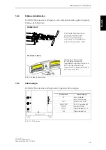
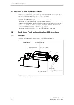
Страница 14: ...zum Schalten und Schützen von Drehstromverbrauchern bei 400 V AC bis zu 4 kW mechanisch schaltend und bis zu 5 5 kW Sanftstarter optional mit Bremskontakt 400 V AC ausgestattet verfügbar mit PROFIBUS DP oder AS Interface AS i Anschluss 1 2 Anschlüsse Feldbus Schnittstellen LED Anzeigen 1 2 1 Anschlüsse ECOFAST Motorstarter verfügen über folgende Anschlüsse Bild 1 1 Anschlüsse am Motorstarter AUX P...

Страница 15: ...OFIBUS DP PROFIBUS DP Schnittstelle mit Datenanschluss und Daten T Steckverbinder wahlweise für Kupferleitung oder Lichtwellenleiter LWL AS Interface Schnittstelle in Schneidklemmtechnik für gelbe AS i Leitung Daten und 24 V nicht geschaltet und schwarze AS i Leitung AUX PWR 24 V DC geschaltet AS Interface AS i AS i AUX PWR AS Interface Beschreibung SF Sammelfehler Sammelwarnung AS i Feldbus Zusta...

Страница 16: ...rsicht 3RK1 323 2AS54 1AA0 3RK1 323 2AS54 1AA3 Graue Felder Beschreibung in diesem Handbuch ECOFAST Motorstarter Best Nr 3RK1702 2GB18 0AA1 Deutsch Englisch Weiße Felder Beschreibung im Handbuch ECOFAST Motorstarter High Feature Best Nr 3RK1702 3AB18 1AA1 Deutsch Best Nr 3RK1702 3BB18 1AA1 Englisch Bestell nummer Gerätefunktion Lokale Geräteschnittstelle Verhalten bei Busausfall Selbsttest Notstar...

Страница 17: ...eitig vorkonfektionierte Energie Kabel mit Han Q4 2 Stift 2 5 2 2 2 Einseitig vorkonfektionierte Energie Kabel mit Han 10E Stift 2 6 2 3 Motoranschluss 2 7 2 3 1 Pinbelegung 2 7 2 3 2 Energie Kabel konfektionieren 2 8 2 4 Energieanschluss 2 9 2 4 1 Pinbelegung 2 9 2 4 2 Energie Kabel konfektionieren 2 10 2 5 Energie T Steckverbinder 2 12 2 6 Digitaleingänge 2 13 2 7 AS i Schnittstelle 2 14 2 7 1 A...

Страница 18: ...rät spannungsfrei Gefahr Achten Sie auf richtige und sorgfältige Verdrahtung Ansonsten können Motorstarter zerstört werden Es besteht Lebensgefahr Vorsicht Beachten Sie dass im Motorstarter bereits Sternbrücken verdrahtet sind Vorsicht Die ECOFAST Motorstarter haben integrierte EMV Schutzbeschaltungen Um Funktionsstörungen zu vermeiden dürfen nur Motoren ohne EMV Schutzbeschaltung an den ECOFAST M...

Страница 19: ...eitungen ergibt sich z B bei Verlegung im Kabelkanal in Abhän gigkeit von der Umgebungstemperatur folgende max Strombelastbarkeit Beachten Sie beim Verdrahten folgende Regeln Tabelle 2 1 Regeln für Verdrahten 30 C 40 C 45 C 50 C 55 C 1 5 mm2 14 A 12 2 A 11 1 A 9 9 A 8 5 A 2 5 mm2 19 A 16 5 A 15 0 A 13 5 A 11 6 A 4 0 mm2 26 A 22 6 A 20 5 A 18 5 A 15 9 A Regeln für flexible Leitungen Daten Strombela...

Страница 20: ...T Motorstarter 2 4 GWA 4NEB 950 5221 12 DS 02 2 1 2 Unbenutzte Anschlüsse Verschließen Sie unbenutzte Anschlüsse mit Verschlusskappen nur so wird die Schutzart IP65 gewährleistet Bestellnummer 3 RK1902 0CJ00 10 St oder 3 RK1902 0CK00 1 St ...

Страница 21: ...Sie die Adern abisolieren und z B einen Steckverbinder oder einen Klemmenblock anschließen Bild 2 1 Aufgedruckte Zahlen auf den Adern der Energie Kabel 2 2 1 Einseitig vorkonfektionierte Energie Kabel mit Han Q4 2 Stift Bild 2 2 Einseitig vorkonfektionierte Energie Kabel mit Han Q4 2 Stift 1 2 4 5 1 1 2 2 4 4 3 3 3 5 5 Die Adern sind mit aufgedruckten Zahlen gekenn zeichnet Die Zuordnung der Zahle...

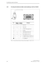
Страница 22: ... 3 Einseitig vorkonfektionierte Motoranschlussleitungen mit Han 10E Stift Pin Ader Nr 7 adrig Ader Nr 11 adrig Belegung 1 1 1 Phase L1 2 2 2 Phase L2 3 3 3 Phase L3 4 4 Bremse Bezugspotential 5 5 Bremse 6 4 6 Wicklungsanschluss W2 7 5 7 Wicklungsanschluss U2 8 6 8 Wicklungsanschluss V2 9 9 Temperatursensor Anschluss a 10 10 Temperatursensor Anschluss b PE gelb grün ...

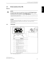
Страница 23: ...lquetschung ausgeschlossen werden kann Vorsicht Sichere Trennung zwischen 400 V AC und 24 V DC ist nur mit einem Motor mit sicherer Trennung des Temperatursensorkreises zur Ständerwicklung gewährleistet 2 3 1 Pinbelegung Bild 2 4 Pinbelegung Motoranschluss 10 9 8 7 6 5 4 3 2 1 Pin Belegung 1 Wicklungsanschluss U1 2 Wicklungsanschluss V1 3 Wicklungsanschluss W1 4 Bremse Bezugspotential 5 Bremse 6 W...

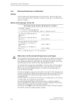
Страница 24: ...en an sichere Trennung erfüllen Die 400 V Energieversorgung für den Motor und die 24 V DC Energieversor gung für die Bremse werden über gemeinsame Kabel und Stecker zum Ver braucher geführt Bei Kabelquetschungen besteht die Gefahr des Span nungsübertrittes Deshalb dürfen an den Bremsstromkreis keine Verbraucher mit der Schutz art Kleinspannung angeschlossen werden Die Versorgungsspannung für die B...

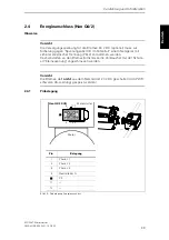
Страница 25: ...etzgerät mit sicherer elektrischer Trennung PELV entnommen werden Deshalb dürfen an den Bremsstromkreis keine Verbraucher mit der Schutz art Kleinspannung angeschlossen werden Vorsicht Die Bremse darf nicht aus dem Netzteil der 24 V DC geschaltet AUX PWR schwarze AS i Leitung gespeist werden 2 4 1 Pinbelegung Bild 2 5 Pinbelegung Energieanschluss Pin Belegung 1 Phase L1 2 Phase L2 3 Phase L3 4 Neu...

Страница 26: ...gie Kabel mit Han Q4 2 Tabelle 2 3 Verbindungsleitungen mit Han Q4 2 konfektionieren Sie benötigen ein flexibles Cu Kabel 5 x 4 mm2 3 Leiter N PE 5 x 6 mm2 3 Leiter N PE Energie Steckverbinder Han Q4 2 Buchse 4 mm2 3RK1911 2BE10 6 mm2 3RK1911 2BE30 Energie Steckverbinder Han Q4 2 Stift 4 mm2 3RK1911 2BF20 6 mm2 3RK1902 2BF40 Energie Steckverbinder Han Q4 2 Buchse 4 mm2 3RK1911 2BR10 6 mm2 3RK1911 ...

Страница 27: ...d verdrahten Schritt Vorgehensweise 1 Führen Sie das Kabel durch die PG Verschraubung den jeweils passenden beiliegenden Dichtungsring und das Steckergehäuse 2 Befestigen Sie die Kontaktbuchsen Kontaktstifte an den Adern 3 Schieben Sie die Kontaktbuchsen Kontaktstifte bis zum Einrasten in den Buchseneinsatz Stifteinsatz 4 Ziehen Sie das Kabel zurück und schrauben Sie den Einsatz mit den beiliegend...

Страница 28: ...nicht unterbrochen Pinbelegung Pinbelegung Energie T Klemmverbinder Klemme Belegung Ader Nr 1 Phase L1 2 Phase L2 3 Phase L3 PE 4 Neutralleiter N 5 reserviert 6 reserviert 2 2 2 3 3 3 4 4 4 1 1 1 1 2 3 4 5 6 Klemmennummern und Han Q4 2 Pinnummern sind in der Belegung nicht identisch 1 2 4 5 1 1 2 2 4 4 3 3 3 5 5 Vorsicht Beachten Sie dass bei vorkonfektionierten Energie Kabeln Adernummern und Klem...

Страница 29: ...e für 2 und 3 Leiter Technik Bild 2 7 Pinbelegung Digitaleingänge mit Schaltungsbeispielen Achtung Die Digitaleingänge sind kurzschlussfest Der Strom wird auf maximal 200 mA begrenzt Bei Kurzschluss oder Überlastung der Sensorversorgung werden Schaltelement Motor und Bremsausgang abgeschaltet und Sam melfehler wird ausgegeben Diesen Fehler müssen Sie mit Trip Reset quit tieren Achtung Verwenden Si...

Страница 30: ...Hilfsenergie 24 V DC Aktor versorgung PELV muss geerdet sein Schema Folgendes Bild zeigt die Lage und Kodierung der AS i Leitungen am Motorstarter Bild 2 8 AS Interface Schnittstelle Kontaktierung Die AS i Leitungen werden mit Hilfe der Durchdringungstechnik automatisch kontaktiert indem der AS i Deckel aufgeschraubt wird Bild 2 9 Kontaktierung der AS i Leitungen AS i AUX PWR AS i Leitung Kommunik...

Страница 31: ...altet Bei Spannungswiederkehr werden Abschaltbefehl sowie die dazugehörigen Melde und Fehlerbits automatisch quittiert Spannungsversorgung 24 V DC AUX PWR geschaltet schwarze AS i Leitung Diese Spannung ist nicht ständig vorhanden Sie wird nur benötigt für die Ansteuerung der Schaltelemente z B einem Schütz Diese Spannung kann bei NOT AUS bzw Sicherheitsabschaltung Kategorie 1 nach EN 954 1 abgesc...

Страница 32: ...reibung Die Adressierbuchse dient zum Adressieren z B mit dem Adressier und Diagnosegerät Dieses wird mit der Verbindungsleitung an der Adressier buchse angeschlossen Bild 2 10 Adressierbuchse Adressierbuchse Verbindungsleitung Verschlusskappe SF AS i AUX PWR STATE IN 1 2 IN 2 ADDR DEVICE X1 X3 Adressierbuchse ...

Страница 33: ...der in der Nähe des Motors aufbauen Motor nah mit Verbindungskabel oder direkt am Motor anstecken Motor angesteckt mit Befestigungsblech Abschnitt Thema Seite 3 1 Adresse einstellen 3 2 3 2 Aufbau Motor angesteckt 3 3 3 2 1 Benötigte Komponenten 3 3 3 2 2 Montage 3 4 3 3 Aufbau Motor nah 3 5 3 3 1 Benötigte Komponenten 3 5 3 3 2 Montage 3 6 ...

Страница 34: ... Code Hex ID1 Code Hex ID2 Code Hex für Erzeugnisstand 1 kleiner 10 ab 10 3RK1323 2AS54 1AA0 7 D F F 0 3RK1323 2AS54 1AA3 7 D F F 0 1 Der Erzeugnisstand ist unter der Adressierbuchse aufgedruckt Schritt Vorgehensweise 1 Wenn der Motorstarter über die Adressierbuchse adressiert werden soll dann schalten Sie die AS i Spannung ab Dies ist aus Gründen der Anla gensicherheit notwendig 2 Schrauben Sie d...

Страница 35: ...je nach Ausführung 2 Befestigungsblech mit Schrauben für Motorstarter 3RK1911 3AA00 3 Energie T Klemmverbinder wahlweise 5 x 4 mm2 5 x 6 mm2 3RK1911 2BF01 3RK1911 2BF02 4 Energie Kabel 3RK1911 0A je nach Länge und Querschnitt 5 AS i Leitung profiliert gelb Gummi 2 x 1 5 mm2 für Feldbus 3RX901 0AA00 je nach Länge 6 AS i Leitung profiliert schwarz Gummi 2 x 1 5 mm2 für ext Hilfsspannung 24 V AUX PWR...

Страница 36: ...estigungsblech auf Schieben Sie den Motorstarter auf den Motorstecker Sichern Sie die Verbindung mit der Verriegelung 3 Schließen Sie die AS i Leitungen an gemäß folgendem Schema Achtung Wenn der Motorstarter der letzte Teilnehmer in der AS Interface Linie ist dann müssen Sie die AS i Leitungen an ihren Enden mit Leitungsendstücken Best Nr 3RK1901 1MN00 abschließen um die Schutzart IP65 zu erreich...

Страница 37: ...anschlussleitung zur Verbindung Motorstarter Motor Han 10E vorkonfektioniert oder selbst konfektioniert 3RK1911 0 je nach Län ge Querschnitt Han 10E einseitig beidseitig 4 Energie T Klemmverbinder wahlweise 5 x 4 mm2 5 x 6 mm2 3RK1911 2BF01 3RK1911 2BF02 5 Energie Kabel 3RK1911 0A je nach Länge und Querschnitt 6 AS i Leitung profiliert gelb Gummi 2 x 1 5 mm2 für Feldbus 3RX901 0AA00 je nach Länge ...

Страница 38: ...ät spannungsfrei Beachten Sie die Informationen in der Betriebsanleitung Führen Sie folgende Schritte aus um den Motorstarter zu montieren Schritt Beschreibung 1 Sehen Sie für die Montage eine plane Fläche vor Abstand vom Motor je nach Länge des Energiekabels Die Einbaulage ist beliebig 2 3 Schrauben Sie den Motorstarter auf der planen Fläche fest Tabelle 3 6 Montage Motor nah 90 210 Bohren Sie 4 ...

Страница 39: ...rreichen Lassen Sie dazu die Leitungsenden ca 10 cm nach der AS Interface Schnitt stelle überstehen 5 Verbinden Sie Motorstarter und Motor mit der Motoranschlussleitung Sichern Sie die Verbindungen mit den Verriegelungen 6 Stecken Sie den Energie T Klemmverbinder am Energieanschluss des Moto starters an Sichern Sie die Verbindung mit der Verriegelung 7 Schließen Sie das Energie Kabel am Energie T ...

Страница 40: ...Montage von Motorstartern ECOFAST Motorstarter 3 8 GWA 4NEB 950 5221 12 DS 02 ...

Страница 41: ...tsch English Inbetriebnahme und Diagnose 4 Abschnitt Thema Seite 4 1 Prozessdaten und Prozessabbilder 4 2 4 2 Inbetriebnahme und Anlauf 4 4 4 3 Diagnose durch LED Anzeige 4 6 4 4 Diagnose mit dem Adressier und Diagnosegerät 4 7 4 5 Verhalten bei Störung 4 7 ...

Страница 42: ... Prozessdaten und Prozessabbild AS Interface Prozessdaten Prozessabbild 4 Ausgänge DO 0 0 bis DO 0 3 4 Eingänge DI 0 0 bis DI 0 3 4 Parameter PO 0 0 bis PO 0 3 Signal 1 HIGH 0 LOW Ausgänge Steuerbefehle SPS zum Motorstarter DO 0 0 Motor RECHTS 1 EIN 0 AUS 1 Motor LINKS 1 EIN 0 AUS 2 Bremse 1 EIN 0 AUS 3 Trip Reset 0 1 AKTIV 0 1 NICHT AKTIV Eingänge Meldungen Motorstarter zur SPS DI 0 0 Bereit Auto...

Страница 43: ...enn Sie den Parameter Verhalten bei Überlast Temperatursensor auf Warnen parametrieren dann stellt der Motorstarter automatisch den Para meter Autoreset auf JA Dadurch wird die Meldung Sammelwarnung nach Beseitigung der Fehlerursache automatisch gelöscht Selbsttestfunktion mit Trip Reset Achtung Wenn Trip Reset Ausgang DO 0 3 länger als 2 Sekunden ansteht und kein Sammelfehler Sammelwarnung vorlie...

Страница 44: ...ormationen finden Sie in der Betriebsanleitung des Adressier und Diagnosegerätes Eingesetzte Projektiersoftware Erläuterungen Projektiersoftware zum eingesetzten AS i Master Siehe Handbuch des AS i Masters Vorausgesetzte Tätigkeit Weitere Informationen siehe 1 Motorstarter montiert Kapitel Montage 2 Adresse am Motorstarter eingestellt Kapitel Montage 3 Versorgungsspannung für den Motorstarter eing...

Страница 45: ...arter einschalten Motorstarter setzt Ausgänge auf 0 und übernimmt die eingestellte Adresse Motorstarter empfängt Projektie rungsdaten vom AS i Master Projektierungsdaten stimmen mit dem realen Aufbau überein Ein und Ausgänge sind freigegeben Datenaustausch ist möglich Abhilfe Projektierungsdaten mit Aufbau abgleichen oder umgekehrt LEDs AS i und AUX PWR leuchten Nein Ja Betriebsbereit ...

Страница 46: ...tion u ungeschalt Versorgung ok aus keine ungeschaltete Versorgungsspannung grün ungeschaltetete Versorgungsspannung ok aus ungeschaltetete Versorgungsspannung nicht ok AUX PWR grün geschaltetete Versorgungsspannung ok aus geschaltetete Versorgungsspannung nicht ok STATE grün Schaltstatus Schaltelement EIN durch Steuerung B B aus Schaltelement AUS rot Schaltzustand Schaltbefehl IN 1 grün Digitalei...

Страница 47: ...delt Tabelle 4 6 Mögliche Fehler und Fehlerbehandlung Mögliche Fehler Aktion Anzeige LEDs Bemerkung Reset Busfehler Abschalten AS i Auto Prozessabbildfehler Abschalten SF AUS Unterspannung AS i Abschalten SF U 18 V Auto Unterspannung AUX PWR Abschalten SF U 18 V Auto Sensorversorgung Überlast Abschalten SF I 200 mA Trip Reset Temperatursensor Überlast Warnen Abschalten SF Auto Autoreset Trip Reset...

Страница 48: ...Sie können folgendermaßen quittieren Mit Trip Reset Ausgang DO 0 3 Trip Reset über Feldbus Mit Gegenbefehl z B Motor Aus Nur bei Prozessabbildfehler Automatisches Quittieren abhängig vom Parameter PO 0 3 Autoreset Nur bei Temperatursensorfehlern Achtung Steht Trip Reset permanent an wird das Quittieren flankengetriggert einmal angestoßen Wenn Trip Reset Ausgang DO 0 3 länger als 2 Sekunden ansteht...

Страница 49: ...ECOFAST Motorstarter GWA 4NEB 950 5221 12 DS 02 5 1 Deutsch English Fehlerbehandlung 5 Abschnitt Thema Seite 5 1 Verhalten bei Störung 5 2 5 1 1 Störungen quittieren 5 3 5 2 Mögliche Fehler 5 4 ...

Страница 50: ...e der Motorstarter je nach Parametrierung reagiert Bild 5 1 Schema Verhalten bei Störung Achtung Bei Störungen wie z B Prozessabbildfehler oder Gerätefehlern wie z B Schaltelement defekt ist das Verhalten bei Störung immer Abschalten Das Verhalten bei Störung ist nicht parametrierbar Störung Reaktion 1 Reaktion 2 Verhalten Warnen Abschalten Meldebit Bereit 0 Bereit 1 LED Anzeige SF aus SF leuchtet...

Страница 51: ...t über Feldbus Mit Gegenbefehl z B Motor Aus Nur bei Prozessabbildfehler Automatisches Quittieren abhängig vom Parameter PO 0 3 Autoreset Nur bei Temperatursensorfehlern Achtung Steht Trip Reset permanent an wird das Quittieren flankengetriggert einmal angestoßen Wenn Trip Reset Ausgang DO 0 3 länger als 2 Sekunden ansteht und kein Sammelfehler Sammelwarnung vorliegt dann wird die Selbsttestfunkti...

Страница 52: ...versorgung überprü fen I Sensor 200mA Temperatursensor Überlast Warnen SF rot Auto Warten bis Motor abgekühlt ist Abschalten SF rot Autoreset Trip Reset Warten bis Motor abgekühlt ist Nach Abkühlung quittieren Wenn Quittierung nicht mög lich ist der Motor noch zu warm Temperatursensor Kurzschluss Warnen SF rot Auto Kurzschluss auf der Tempe ratursensorleitung entfer nen Abschalten SF rot Autoreset...

Страница 53: ...B 950 5221 12 DS 02 6 1 Deutsch English Gerätefunktionen 6 Abschnitt Thema Seite 6 1 Temperatursensor 6 2 6 2 Steuerfunktion Reversierstarter 6 3 6 3 Bremsverfahren mechanisch 6 4 6 4 Schalttechnologie elektronisch mechanisch 6 5 ...

Страница 54: ...parametriertem Temperatursensor Thermoclick nur bei 3RK1323 2AS54 1AA kann es bei längerer spannungsloser Zeit 10 Stunden der nicht geschalteten Hilfsenergie zu einem Sammelfehler Sammelwarnung kommen Dieser kann über Ziehen Stecken des Thermistorkreises rückgesetzt werden Bei Verwendung der PTC Auswertung oder High Feature Startern tritt dieses Verhalten nicht auf Parameter Verhalten bei Überlast...

Страница 55: ...ndere erst nach einer bestimmten Zeitverzögerung umgeschaltet werden darf Während dieser Zeitverzögerung soll die Schwungmasse des Antriebs zum Stillstand kom men Die Zeitverzögerung ist abhängig vom verwendeten Antrieb und muss im Applikationsprogramm entsprechend berücksichtigt werden Ausgänge zum Steuern Mit den beiden Ausgängen DO 0 0 und DO 0 1 wird die Drehrichtung gesteuert Motor RECHTS DO ...

Страница 56: ...l für Bremsverfahren mechanisch Bild 6 1 Schaltungsbeispiel Bremsverfahren mechanisch Ausgang zum Steuern Mit dem Ausgang DO 0 2 wird die Bremse gesteuert Bremse DO 0 2 1 EIN 0 AUS 10 9 8 7 6 5 4 3 2 1 Pin Belegung 1 Wicklungsanschluss U1 2 Wicklungsanschluss V1 3 Wicklungsanschluss W1 4 Bremse Bezugspotential 5 Bremse 6 Wicklungsanschluss W2 7 Wicklungsanschluss U2 8 Wicklungsanschluss V2 9 Tempe...

Страница 57: ...nes defekten Schaltelements Schütz verschweißt Thyristor durchlegiert ist es dem Motorstarter nicht mehr möglich den Motor abzuschalten Hinweis Werten Sie ggf die Meldung Schaltelement defekt aus und schalten Sie in Abhängigkeit davon den Abzweig durch ein vorgelagertes Schaltelement ab Mögliche Fehlerursachen Die Gerätefunktion Schalttechnologie liefert die Meldung Sammelfehler bei folgenden Fehl...

Страница 58: ...Gerätefunktionen ECOFAST Motorstarter 6 6 GWA 4NEB 950 5221 12 DS 02 ...

Страница 59: ...1 Deutsch English Technische Daten A Abschnitt Thema Seite A 1 Motorstarter A 2 A 1 1 Allgemeine technische Daten A 2 A 1 2 Hilfsenergie A 5 A 1 3 Digitaleingänge A 5 A 1 4 Bremsausgang 400 V AC A 5 A 1 5 Hauptenergie A 6 A 1 6 Mechanisch Schalten A 6 ...

Страница 60: ...peratur 40 C bis 80 C Relative Luftfeuchte 5 bis 95 Betauung nicht zulässig Aufstellungshöhe max 1000 m 2000 m Ohne Einschränkungen Mit Einschränkungen Reduzierung von Ie um 1 100 m bis 2000 m Schwingbeanspruchung f 5 bis 26 Hz d 0 75 mm f 26 bis 150 Hz a 2 g 10 Zyklen Schock a 120 m s2 12 g mit 11 ms je 3 Schock in allen Achsen 18 ESD 8 kV Luftentladung 6 kV Kontaktentladung IEC 1000 4 2 Schärfeg...

Страница 61: ... Schalthäufigkeit ermittelt werden Maximale Schalthäufigkeit bei Ia 4 x Ie mit Beispiel Bild A 2 Maximale Schalthäufigkeit bei Ia 4 x Ie mit Beispiel Ia Ie ta tb tED tp ts Belastungsdiagramm Ia Direktanlaufstrom des Motors Ie Bemessungsbetriebsstrom des Motors ta Anlaufzeit des Motors tb Betriebszeit tp Pausenzeit tED Einschaltdauer ts Schaltspiel ED tED ts x 100 Beispiel Einschaltdauer 1 s Anlauf...

Страница 62: ...Technische Daten ECOFAST Motorstarter A 4 GWA 4NEB 950 5221 12 DS 02 Maximale Schalthäufigkeit bei Ia 6 x Ie und Ia 7 19 x Ie Bild A 3 Maximale Schalthäufigkeit bei Ia 6 x Ie und Ia 7 19 x Ie ...

Страница 63: ...tz aus typisch bei Duo Reversiersanftstartern 80 mA PROFIBUS DP 60 mA AS Interface 75 mA 15 mA 110 mA Verpolungsschutz ja Gerät funktioniert jedoch nicht Kurzschlussschutz Überlastschutz ja Multifuse 0 5 A selbstheilende Sicherung Zurücksetzen durch Power OFF Unterspannungserkennung USP 17 V DC 17 V DC Spannungsausfall Überbrückung 20 ms Gerät wird nicht beinflusst Isolationsspannung 500 V DC zwis...

Страница 64: ...Einschaltdauer ED 100 Gebrauchskategorie 1 Gerät nach Kurzschluss zerstört Betriebsspannung 3 AC 200 V 10 bis 460 V 10 Betriebsstrom 0 3 A bis 9 A 0 3 A bis 7 3 A 0 3 A bis 6 7 A Class 10 Class 20 Class 30 Schaltvermögen AC 3 9 0 A AC 4 6 5 A Schalten Last 3 phasig mit SIMICONT Schütz Kurzschlussschutz Schmelzsicherung am 16 A 500 VAC ICu 120 kA Lebensdauer Schaltelement 0 4 x 10⁶ bei Ie 9 0 A 1 1...

Страница 65: ...ECOFAST Motorstarter GWA 4NEB 950 5221 12 DS 02 B 1 Deutsch English Maßbilder B Abschnitt Thema Seite B 1 Motorstarter B 2 ...

Страница 66: ...ECOFAST Motorstarter B 2 GWA 4NEB 950 5221 12 DS 02 B 1 Motorstarter Bild B 1 Maßbild Motorstarter ...

Страница 67: ...A 4NEB 950 5221 12 DS 02 C 1 Deutsch English Bestellnummern C Abschnitt Thema Seite C 1 Motorstarter Reversierstarter C 2 C 2 Daten T Verbinder C 3 C 3 Zubehör für Motorstarter C 3 C 4 Projektiersoftware und Dokumentation C 4 ...

Страница 68: ...0 3 A 3 A 1 1 kW Thermisches Motormodell Mechanisch AS Interface 3RK1323 5BS44 3AA0 2 4 A 9 A 4 kW AS Interface 3RK1323 5CS44 3AA0 0 3 A 3 A 1 1 kW 400 V AC AS Interface 3RK1323 5BS44 3AA3 2 4 A 9 A 4 kW 400 V AC AS Interface 3RK1323 5CS44 3AA3 0 3 A 3 A 1 1 kW Motorvollschutz Elektronisch Sanft PROFIBUS DP 3RK1303 6BS74 3AA0 2 4 A 12 A 5 5 kW PROFIBUS DP 3RK1303 6DS74 3AA0 0 3 A 3 A 1 1 kW 400 V ...

Страница 69: ...ichermodul 1 3RK1911 0BN20 Teststecker Set 1 3RK1911 2AM00 Tabelle C 3 Bestellnummern für Zubehör für Motorstarter Beschreibung Bestellnummer Projektiersoftware Switch ES Motorstarter Switch ES Motorstarter 2004 zum Parametrieren Beobachten Diagnostizierung und Testen der ECOFAST Motorstarter über PROFIBUS DP mit Online Hilfe deutsch englisch umschaltbar getestet auf Ablauf unter Windows 2000 XP P...

Страница 70: ...Bestellnummern ECOFAST Motorstarter C 4 GWA 4NEB 950 5221 12 DS 02 ...

Страница 71: ... 2 5 Einseitig vorkonfektionierte Motoran schlussleitungen mit Han 10E Stift 2 6 Energieanschluss 2 9 Energie Kabel konfektionieren 2 10 Energie Kabel mit HanQ8 2 10 Energie Steckverbinder Han Q8 2 11 Energie Steckverbinder montieren und verdrahten 2 11 Energie T Steckverbinder 2 12 F Fehler 4 7 Feldbus Schnittstellen 1 3 Hauptenergie A 6 Hilfsenergie A 5 I Inbetriebnahme und Anlauf 4 4 L LED Anze...

Страница 72: ...0 5221 12 DS 02 T Technische Daten A 2 Temperatursensor 6 2 Temperatursensorleitungen 2 8 Testen der Verdrahtung 4 4 Thermocklick 6 2 Trip Reset 4 3 4 8 V Verhalten bei Spannungsausfall 2 15 Verhalten bei Störung 4 7 5 2 Verschlusskappen 2 4 ...

Страница 73: ...0 Amberg Fax 09621 80 3337 Systemhandbuch ECOFAST Motorstarter Sind Sie beim Lesen dieses Handbuches auf Fehler gestoßen Bitte teilen Sie uns diese Fehler auf diesem Vordruck mit Für Anregungen und Verbesserungsvorschläge sind wir Ihnen dankbar Absender bitte ausfüllen Name Firma Dienststelle Anschrift Telefon ...

Страница 74: ...Korrekturblatt ECOFAST Motorstarter GWA 4NEB 950 5221 12 DS 01 ...

Страница 75: ...rs Overview 1 Wiring and interfaces 2 Installing Motor Starters 3 Commissioning and diagnostics 4 Fault Handling 5 Device functions 6 Technical data A Dimension drawings B Order numbers C Edition 04 2009 ECOFAST Motor Starters Manual Order No 3RK1702 2GB18 0AA1 ...

Страница 76: ...other manufacturers which have been approved or recommended by Siemens This product can only function correctly and safely if it is transported stored set up and installed correctly and operated and maintained as recommended Brands SIMATIC SIMATIC HMI ECOFAST and SIMATIC NET are brands of SIEMENS AG Han Brid Han Q4 2 Han 10E are brands of Harting company Some other designations used in these docum...

Страница 77: ...Pin 2 6 2 3 Motor terminal Han 10E 2 7 2 3 1 Pin assignment 2 7 2 3 2 Prefabricating Motor Connection Cables 2 8 2 4 Power terminal 2 9 2 4 1 Pin assignment 2 9 2 4 2 Preparing power cables 2 10 2 5 Power tee clamping connectors 2 12 2 6 Digital inputs 2 13 2 7 AS Interface 2 14 2 7 1 Connection techniques 2 14 2 7 2 Behavior in the event of a power failure 2 15 2 8 Addressing socket 2 16 3 Instal...

Страница 78: ... braking 6 4 6 4 Electronic mechanical switching technology 6 5 A Technical data A 1 A 1 Motor Starters A 2 A 1 1 General technical data A 2 A 1 2 Auxiliary power A 5 A 1 3 Digital inputs A 5 A 1 4 Brake output 400 V AC A 5 A 1 5 Main power A 6 A 1 6 Mechanical switching A 6 B Dimension drawings B 1 B 1 Motor Starter B 2 C Order numbers C 1 C 1 Motor Starters Reversing starters C 2 C 2 Data Tee Co...

Страница 79: ...r motor terminal 2 7 Fig 2 5 Pin assignment for power terminal 2 9 Fig 2 6 Han Q4 2 power connector 2 11 Fig 2 7 Pin assignment for power tee clamping connector 2 12 Fig 2 8 Pin assignment with circuit examples 2 13 Fig 2 9 AS i interface 2 14 Fig 2 10 Contacting the AS i cables 2 14 Fig 2 11 Addressing socket 2 16 Fig 4 1 Starting the motor starter 4 5 Fig 5 1 Responding to faults 5 2 Fig 6 1 Typ...

Страница 80: ...motor plugged in 3 4 Table 3 5 Components required for setting up with the motor nearby 3 5 Table 3 6 Installation motor nearby 3 6 Table 4 1 Process data and process image AS Interface 4 2 Table 4 2 Software requirements for commissioning 4 4 Table 4 3 Requirements for commissioning 4 4 Table 4 4 Testing the wiring from the motor starter to the motor 4 4 Table 4 5 Diagnostics through LED indicato...

Страница 81: ...ers providing instructions for use and that can be used for reference The following topics are covered Motor starters overview Wiring and interfaces Installation of motor starters Commissioning and diagnostics Fault handling Device functions Technical data Dimension drawings Order numbers Specifications This manual only describes the ECOFAST Motor Starter The terms ECOFAST Motor Starter and Motor ...

Страница 82: ...ve motor connector Han 10E motor terminal Mounting plate Han 10E motor terminal Han Drive motor connector alternative terminal block Han 10E alternative free end for connection to prefabricated at both ends alternative prefabricated at one end and other end free terminal block Motor plugged in Motor starter directly on the motor Motor nearby Motor starter and motor connected with cable ...

Страница 83: ...otor starter please observe the installation guidelines in the ECOFAST system manual Other system manuals For more information on ECOFAST see the following system manual System ECOFAST Correction page At the end of this manual is a correction page Please use this page to note your suggestions for improvements additional information or corrections and send the page back to us In this way you will h...

Страница 84: ...ECOFAST Motor Starters viii GWA 4NEB 950 5221 12 DS 02 ...

Страница 85: ...ect Page 1 1 What are ECOFAST Motor Starters 1 2 1 2 Connections fieldbus interfaces LED indicators 1 2 1 2 1 Connections 1 2 1 2 2 Fieldbus interfaces 1 3 1 2 3 LED indicators 1 3 1 3 Product overview 1 4 1 3 1 General Notes 1 4 1 3 2 Product Overview Individual Motor Starters and Their Device Functions 1 5 ...

Страница 86: ...d protecting three phase loads rated at 400 V AC up to 4 kW mechanical switching and up to 5 5 kW soft starter optionally equipped with a 400 V AC brake contact available with a PROFIBUS DP or AS Interface AS i connection 1 2 Connections fieldbus interfaces LED indicators 1 2 1 Connections ECOFAST Motor Starters have following connections Fig 1 1 Connections on the motor starter AUX PWR AS i Motor...

Страница 87: ...3 LED indicators PROFIBUS DP PROFIBUS DP interface with data terminal and data tee connector optionally for copper cable or fiber optic cable AS i interface using insulation displacement technology for yellow AS i cable data and 24 V non switched and black AS i cable AUX PWR 24 V DC switched AS Interface AS i AS i AUX PWR AS Interface Description SF General fault AS i Fieldbus status AUX PWR 24 V ...

Страница 88: ...starters 3RK1 323 2AS54 1AA0 3RK1 323 2AS54 1AA3 Grey fields Description in this manual ECOFAST Motor Starters Order no 3RK1702 2GB18 0AA1 German English White fields Description in manual ECOFAST Motor Starters High Feature Order no 3RK1702 3AB18 1AA1 German Order no 3RK1702 3BB18 1AA1 English Order number Device function Local device interface Response to bus failure Self test Emergency start In...

Страница 89: ...refabricated at One End with Han Q4 2 Pin 2 5 2 2 2 Power Cables Prefabricated at One End with Han 10E Pin 2 6 2 3 Motor Terminal 2 7 2 3 1 Pin Assignment 2 7 2 3 2 Prefabricating Power Cables 2 8 2 4 Power Terminal 2 9 2 4 1 Pin Assignment 2 9 2 4 2 Prefabricating Power Cables 2 10 2 5 Power Tee Connectors 2 12 2 6 Digital Inputs 2 13 2 7 AS Interface 2 14 2 7 1 Connection Techniques 2 14 2 7 2 R...

Страница 90: ...Danger Ensure that the wiring is carried out carefully and correctly Otherwise motor starters may be destroyed There is potentially lethal danger Caution Note that star jumpers are already wired in the motor starter Caution ECOFAST motor starters have an integrated EMC protective circuitry To avoid malfunctioning only motors without EMC protective circuitry are to be operated together with ECOFAST...

Страница 91: ...ble duct for example the maximum current carrying capacity as a function of ambient temperature is as follows Observe the following rules when carrying out wiring Table 2 1 Rules for wiring 30 C 40 C 45 C 50 C 55 C 1 5 mm2 14 A 12 2 A 11 1 A 9 9 A 8 5 A 2 5 mm2 19 A 16 5 A 15 0 A 13 5 A 11 6 A 4 0 mm2 26 A 22 6 A 20 5 A 18 5 A 15 9 A Rules for flexible cables Data Current carrying capacity of the ...

Страница 92: ...Starters 2 4 GWA 4NEB 950 5221 12 DS 02 2 1 2 Unused Connections Close off unused connections with screw caps this is the only way of ensuring degree of protection IP65 Order number 3RK1902 0CJ00 10 screw caps or 3RK1902 0CK00 1 screw cap ...

Страница 93: ...n strip the cores and for example attach a plug connector or terminal block Fig 2 1 Numbers printed on the power cable cores 2 2 1 Power Cables Prefabricated at One End with Han Q4 2 Pin Fig 2 2 Power cables prefabricated at one end with Han Q4 2 pin 1 2 4 5 1 1 2 2 4 4 3 3 3 5 5 Numbers are printed on the cores for identification purposes The core number pin assignments are specified in the follo...

Страница 94: ...ower cables prefabricated at one end with Han 10E pin Pin Core no 7 core Core no 11 core Assignment 1 1 1 Phase L1 2 2 2 Phase L2 3 3 3 Phase L3 4 4 Brake reference potential 5 5 Brake 6 4 6 Winding terminal W2 7 5 7 Winding terminal U2 8 6 8 Winding terminal V2 9 9 Temperature sensor terminal a 10 10 Temperature sensor terminal b PE yellow green ...

Страница 95: ...able cannot get jammed or squashed Caution Safe separation between 400 V AC and 24 V DC is only guaranteed on a motor with safe separation of the temperature sensor circuit with respect to the stator winding 2 3 1 Pin assignment Fig 2 4 Pin assignment for motor terminal 10 9 8 7 6 5 4 3 2 1 Pin Assignment 1 Winding terminal U1 2 Winding terminal V1 3 Winding terminal W1 4 Brake reference potential...

Страница 96: ...or in the motor must satisfy the requirements for safe separation The 400 V power supply for the motor and the 24 V DC power supply for the brake are taken over common cables and plug connectors to the loads If the cables are pinched there is a risk of voltage transfer That is why loads with degree of protection Extra low voltage must not be connected to the brake circuit As safeguard against acci...

Страница 97: ...against accidental voltage transfer in the event of a fault It is therefore not permissible to connect any loads with the extra low voltage degree of protection to the braking circuit Caution The brake must not be fed from the power supply unit of the 24 V DC swit ched supply AUX PWR black AS i cable 2 4 1 Pin assignment Fig 2 5 Pin assignment for power terminal Pin Assignment 1 Phase L1 2 Phase L...

Страница 98: ...eads with Han Q4 2 You need for connecting the main power on the motor starter power tee connector for looping through the main power from the power tee connector A flexible Cu cable 5 x 4 mm2 3 conductors N PE 5 x 6 mm2 3 conductors N PE Power connector Han Q4 2 socket 4 mm2 3RK1911 2BE10 6 mm2 3RK1911 2BE30 Power connector Han Q4 2 pin 4 mm2 3RK1911 2BF20 6 mm2 3RK1902 2BF40 Power connector Han ...

Страница 99: ... connectors Step Procedure 1 Guide the cable through the heavy gauge threaded joint the matching enc losed sealing ring in each case and the connector housing 2 Attach the jacks contact pins to the strands 3 Push the jacks contact pins into the socket insert pin insert until they snap into place 4 Pull the cable back and screw the insert in place in the connector housing with the enclosed screws 5...

Страница 100: ...tor starter is unplugged Pin assignment Fig 2 7 Pin assignment for power tee clamping connector Pin Assignment Wire No 1 Phase L1 2 Phase L2 3 Phase L3 PE 4 Neutral N 5 reserved 6 reserved 2 2 2 3 3 3 4 4 4 1 1 1 1 2 3 4 5 6 1 2 4 5 1 1 2 2 4 4 3 3 3 5 5 Caution Note that core numbers and terminal numbers are not identical for prefabricated power cables Wire No Terminal numbers and Han Q4 2 pin nu...

Страница 101: ...r 2 and 3 wire circuits Fig 2 8 Pin assignment with circuit examples Attention The digital inputs are short circuit proof The current is limited to a maximum of 200 mA In the event of a short circuit or overloading of the sensor supply the switching element motor and brake output are deactiva ted and a general fault is issued You must acknowledge this fault with trip reset Attention Do not use an ...

Страница 102: ...uxiliary power for supplying actuators PELV must be grounded Schematic arrangement The diagram below shows the position and coding of the AS i cables on the motor starter Fig 2 9 AS i interface Contacting The AS i cables are contacted automatically using the insulation piercing method when the AS i cover is screwed on Fig 2 10 Contacting the AS i cables AS i AUX PWR AS i cable Communication and no...

Страница 103: ...en the supply is restored the disconnection command and the associated signal bits and error bits are acknowledged automatically 24 V DC voltage supply AUX PWR switched black AS i cable This voltage is not constantly available It is only required for driving the switching elements e g a contactor The voltage can be disconnected in the event of an emergency stop or safety shutdown category 1 accord...

Страница 104: ... The addressing socket is used for addressing with a device such as the addressing and diagnostic unit This is connected to the addressing socket with the connecting lead Fig 2 11 Addressing socket Addressing socket Connecting lead Screw cap SF AS i AUX PWR STATE IN 1 2 IN 2 ADDR DEVICE X1 X3 Addressing socket ...

Страница 105: ...in the vicinity of the motor motor nearby with connecting cable or plug it into the motor directly motor plugged in with mounting plate Section Subject Page 3 1 Setting the address 3 2 3 2 Setup with motor plugged in 3 3 3 2 1 Required components 3 3 3 2 2 Installation 3 4 3 3 Setup with motor nearby 3 5 3 3 1 Required components 3 5 3 3 2 Installation 3 6 ...

Страница 106: ...o I O configu ration hex ID Code hex ID1 Code hex ID2 Code hex of product status1 smaller 10 from 10 3RK1323 2AS54 1AA0 7 D F F 0 3RK1323 2AS54 1AA3 7 D F F 0 1 The product status is printed below the addressing socket Step Procedure 1 If you intend to address the motor starter via the addressing socket switch off the AS i supply voltage This is necessary for reasons of system safety 2 Unscrew the...

Страница 107: ...ing on version 2 Mounting plate with screws for motor starter 3RK1911 3AA00 3 Power T clamping connector optional 5 x 4 mm2 5 x 6 mm2 3RK1911 2BF01 3RK1911 2BF02 4 Power cable 3RK1911 0A depending on the length and cross section 5 AS i cable trapezoidal section yellow rubber 2 x 1 5 mm2 for fieldbus 3RX901 0AA00 depending on length 6 AS i cable trapezoidal section black rubber 2 x 1 5 mm2 for ext ...

Страница 108: ...nting plate Push the motor starter onto the motor connector Secure the connection with the locking device 3 Connect the AS i cables in accordance with the diagram below Attention If the motor starter is the last station on the AS Interface line you must terminate the ends of the AS i cables with cable end covers Order No 3RK1901 1MN00 in order to obtain degree of protection IP65 To allow this leav...

Страница 109: ...r connection cable for motor starter motor connection Han 10E prefabricated or prepared by customer 3RK1911 0 depending on length cross section Han 10E one end both ends 4 Power T clamping connector optional 5 x 4 mm2 5 x 6 mm2 3RK1911 2BF01 3RK1911 2BF02 Power cable 3RK1911 0A depending on the length and cross section 5 AS i cable trapezoidal section yellow rubber 2 x 1 5 mm2 for fieldbus 3RX901 ...

Страница 110: ... work Take note of the information in the operating instructions Work through the following steps to install the motor starter Step Description 1 Choose a flat surface for installation The distance from the motor depends on the length of the power cable Any required mounting position can be chosen 2 3 Screw the motor starter down onto the flat surface Table 3 6 Installation motor nearby 90 210 Dri...

Страница 111: ...5 To allow this leave the cable ends projecting by about 10 cm beyond the AS inter face 5 Connect the motor starter and motor with the motor connecting cable Secure the connections with the locking devices 6 Connect the data lines to the data tee connector Secure the connection with the locking device 7 Connect the terminating connector to the last load feeder non assigned con nection on the last ...

Страница 112: ...Installation of Motor Starters ECOFAST Motor Starters 3 8 GWA 4NEB 950 5221 12 DS 02 ...

Страница 113: ... Commissioning and diagnostics 4 Section Subject Page 4 1 Process data and process images 4 2 4 2 Commissioning and starting 4 4 4 3 Diagnostics through LED indicators 4 6 4 4 Diagnostics with the addressing and diagnostic unit 4 7 4 5 Behavior in the event of faults 4 7 ...

Страница 114: ...ges Table 4 1 Process data and process image AS Interface Process data Process image 4 outputs DO 0 0 to DO 0 3 4 inputs DI 0 0 to DI 0 3 4 parameters PO 0 0 to PO 0 3 Signal 1 HIGH 0 LOW Outputs Control commands PLC to motor starter DO 0 0 Motor CW 1 ON 0 OFF 1 Motor CCW 1 ON 0 OFF 2 Brake 1 ON 0 OFF 3 Trip Reset 0 1 ACTIVE 0 1 NOT ACTIVE Inputs Signals motor starter to PLC DI 0 0 Ready automatic...

Страница 115: ...vior in the event of overload temperature sensor para meter to Warn the motor starter automatically sets the Auto reset para meter to YES As a result the General warning signal is automatically cleared after the cause of the fault is eliminated Self test function with trip reset Attention If trip reset output DO 0 3 is applied for longer than 2 seconds and there is no general fault general warning...

Страница 116: ...urther information is provided in the operating instructions for the addressing and diagnostic unit Configuration software used Explanations Configuration software for the AS i master used See AS i master manual Action assumed to have been taken Further information see 1 Motor starter installed Installation chapter 2 Address set on the motor starter Installation chapter 3 Supply voltage for the mo...

Страница 117: ...n supply voltage for motor starter Motor starter sets outputs to 0 and accepts the set address Motor starter receives configurati on data from AS i master Does the configuration data match the actual setup Inputs and outputs enabled data exchange is possible Remedy match configuration data to setup or vice versa AS i and AUX PWR LEDs light up No Yes Ready for operation ...

Страница 118: ... flashing Zero address green Communication and unswitched supply ok off No unswitched supply voltage green Unswitched supply voltage ok off Unswitched supply voltage not ok AUX PWR green Switched supply voltage ok off Switched supply voltage not ok STATE green Circuit state switching element ON by control HMI off Switching element OFF red Circuit state switching command IN 1 green Digital input 1 ...

Страница 119: ...t with as follows Table 4 6 Possible faults and fault handling Possible fault Action Indication LEDs Comment Reset Bus fault Tripping AS i Auto Process image fault Tripping SF OFF Undervoltage AS i Tripping SF U 18 V Auto Undervoltage AUX PWR Tripping SF U 18 V Auto Sensor supply overload Tripping SF I 200 mA Trip reset Temperature sensor overload Warning tripping SF Auto Auto reset Trip reset Tem...

Страница 120: ...ys With Trip reset output DO 0 3 Trip reset via fieldbus With a counter command e g Motor off only in the case of a process image fault Automatic acknowledgement depending on parameter PO 0 3 Auto reset only in the case of temperature sensor faults Attention If trip reset is applied constantly the acknowledgement is triggered once by edge triggering If trip reset output DO 0 3 is applied for longe...

Страница 121: ...ECOFAST Motor Starters GWA 4NEB 950 5221 12 DS 02 5 1 Deutsch English Fault Handling 5 Section Topic Page 5 1 Responding to Faults 5 2 5 1 1 Acknowledging Faults 5 3 5 2 Potential Faults 5 4 ...

Страница 122: ...motor starter responds depen ding on how it has been parameterized Fig 5 1 Responding to faults Attention In the event of a fault Process image error or device fault Switching ele ment defective the response is always trip Responses to faults cannot be parameterized Fault Reaction 1 Reaction 2 Response Warning Trip Signaling bit General warning set General fault set LED indicator DEVICE flashes ye...

Страница 123: ...nd e g Motor off process image errors only Automatic acknowledgement depending on the PO 0 3 Autoreset parameter only valid for temperature sensor errors Attention If trip reset is applied constantly the acknowledgement is triggered once by edge triggering If trip reset output DO 0 3 is applied for longer than 2 seconds and there is no general fault general warning present the self test function i...

Страница 124: ...ck the sensor supply I Sensor 200 mA Temperature sensor overload Warning SF red Auto Wait until the motor has cooled down Trip SF red Autoreset trip reset Wait until the motor has cooled down Acknowledge after motor has cooled down If acknowledgement is not pos sible the motor is still too hot Temperature sensor short circuit Warning SF red Auto Remove the short circuit on the temperature sensor l...

Страница 125: ...NEB 950 5221 12 DS 02 6 1 Deutsch English Device functions 6 Section Subject Page 6 1 Temperature sensor 6 2 6 2 Reversing starter control function 6 3 6 3 Mechanical braking 6 4 6 4 Electronic mechanical switching technology 6 5 ...

Страница 126: ...ized for Thermoclick temperature sensors 3RK1323 2AS54 1AA only is disconnected from the voltage supply auxili ary power supply for more than 10 hours a group error general warning can occur This group error can be reset by disconnecting and then reconnecting the thermistor circuit This problem does not occur with Low Feature starters which are parameteri zed for PTC temperature sensors or with Hi...

Страница 127: ...ly permissible to switch from one direction of rota tion to the other after a certain delay During this delay the flywheel of the drive is supposed to come to a standstill The length of the delay depends on which drive is being used and must be taken into account accordingly in the application program Control outputs The direction of rotation is controlled with two outputs DO 0 0 and DO 0 1 Motor ...

Страница 128: ...ical circuit for mechanical braking Fig 6 1 Typical circuit for mechanical braking Control output The brake is controlled with output DO 0 2 Brake DO 0 2 1 ON 0 OFF M 3 L1 L2 L3 AC Brake output 10 9 8 7 6 5 4 3 2 1 Pin Assignment 1 Winding terminal U1 2 Winding terminal V1 3 Winding terminal W1 4 Brake reference potential 5 Brake 6 Winding terminal W2 7 Winding terminal U2 8 Winding terminal V2 9 ...

Страница 129: ...ntact block defective If a contact block is defective contactor welded thyristor failure the motor starter cannot shut down the motor Note If necessary evaluate the message Switching element defective and shut down the branch on the basis of this by means of an upstream contact block Possible causes of faults The Switching technology device function returns the General fault signal in response to ...

Страница 130: ...Device functions ECOFAST Motor Starters 6 6 GWA 4NEB 950 5221 12 DS 02 ...

Страница 131: ...2 A 1 Deutsch English Technical data A Section Subject Page A 1 Motor Starters A 2 A 1 1 General Technical Data A 2 A 1 2 Auxiliary Power A 5 A 1 3 Digital Inputs A 5 A 1 4 Brake Output 400 V AC A 5 A 1 5 Main Power A 6 A 1 6 Mechanical switching A 6 ...

Страница 132: ...ting temperature 20 C to 40 C Storage transport temperature 40 C to 80 C Relative humidity 5 to 95 Do not allow condensation to form Site altitude 2000 m 4000 m Without restrictions With restrictions Reduction of Ie by 1 per 100 m to 2 000 m Vibration strain f 5 to 26 Hz d 0 75 mm f 26 to 150 Hz a 2 g 10 cycles Shock a 120 m s2 12 g 11 ms duration 3 shocks per direction in all of the three perpend...

Страница 133: ...sed in a household setting this device can cause radio interfe rence Therefore the user may have to carry out respective measures to avoid such interference Technical data ECOFAST Motor Starters GWA 4NEB 950 5221 12 DS 02 A 3 Deutsch English ...

Страница 134: ...le Ia Ie ta tb tED tp ts Load diagram Ia Direct motor starting current Ie Rated motor operational current ta Motor starting time tb Operating time tp Idle time tED Cyclic duration factor ts Operating cycle ED tED ts x 100 Thermal motor model Class Example Cyclic duration factor 1 s starting time ta 0 1 s Ie 6 A mechanical switching Determined switching frequency approx 1300 switching cycles h Limi...

Страница 135: ...ncy when Ia 6 x Ie and Ia 7 19 x Ie Maximum switching frequency when Ia 6 x Ie Limitation for devices with mech switching elements 0 1 1 10 100 1000 10000 Cyclic duration factor tED in s Switching cycles h Switching cycles h Cyclic duration factor tED in s 0 1 1 10 100 1000 10000 Limitation for devices with mech switching elements Maximum switching frequency when Ia 7 19 x Ie ...

Страница 136: ... element contactor deactivated Typical with Duo reversing softstarters 80 mA PROFIBUS DP 60 mA AS Interface 75 mA 15 mA 110 mA Polarity reversal protection Yes device will not function however Short circuit protection overload protection Yes 0 5 A multifuse self healing fuse Reset by power OFF Undervoltage detection USP 17 V DC 17 V DC Bridging of power failure 20 ms device is not affected Insulat...

Страница 137: ...rcuit protection Fusible link am 16 A 500VAC Ik 120kA Utilization category 1 Device destroyed after short circuit Operating voltage 3 AC 200 V 10 to 460 V 10 Operating current 0 3 A to 9 A 0 3 A to 7 3 A 0 3 A to 6 7 A Class 10 Class 20 Class 30 Switching capacity AC 3 9 0 A AC 4 6 5 A Switching load 3 phase with SIMICONT contactor Short circuit protection Fusible link am 16 A 500 VAC ICu 120 kA L...

Страница 138: ...Technical data ECOFAST Motor Starters A 8 GWA 4NEB 950 5221 12 DS 02 ...

Страница 139: ...ECOFAST Motor Starters GWA 4NEB 950 5221 12 DS 02 B 1 Deutsch English Dimension drawings B Section Subject Page B 1 Motor Sarter B 2 ...

Страница 140: ...ECOFAST Motor Starters B 2 GWA 4NEB 950 5221 12 DS 02 B 1 Motor Starter Fig B 1 Motor starter dimension drawing ...

Страница 141: ... 4NEB 950 5221 12 DS 02 C 1 Deutsch English Order numbers C Section Topic Page C 1 Motor Starters Reversing starters C 2 C 2 Data Tee Connectors C 3 C 3 Accessories for Motor Starters C 3 C 4 Project engineering software and Documentation C 4 ...

Страница 142: ... A 1 1 kW Thermal Motor Model Mechanical AS Interface 3RK1323 5BS44 3AA0 2 4 A 9 A 4 kW AS Interface 3RK1323 5CS44 3AA0 0 3 A 3 A 1 1 kW 400 V AC AS Interface 3RK1323 5BS44 3AA3 2 4 A 9 A 4 kW 400 V AC AS Interface 3RK1323 5CS44 3AA3 0 3 A 3 A 1 1 kW Full Motor Protection Electronic Soft PROFIBUS DP 3RK1303 6BS74 3AA0 2 4 A 12 A 5 5 kW PROFIBUS DP 3RK1303 6DS74 3AA0 0 3 A 3 A 1 1 kW 400 V AC PROFI...

Страница 143: ...Order No Data 24 V Data Tee Connector Cu 3RK1911 2AG00 Data Tee Connector FO 3RK1911 2AH00 Table C 2 Order numbers for Connectors Description Order No Mounting plate for motor plugged in 3RK1911 3AA00 Identification Plug 6ES7194 1KB00 0XA0 PC cable with memory submodule 3RK1911 0BN20 Test connector set 3RK1911 2AM00 Table C 3 Order numbers for accessories ...

Страница 144: ...14 new CP card and MPI interface on PG7xx and its driver software view interactive catalog CA01 CD ROM drive STEP7 object manager for integrating the ECOFAST starter as an S7 slave in SIMATIC S7 for calling Switch ES from STEP7 System requirements SIMATIC S7 M7 C7 PCS7 STEP7 Version 5 0 or higher CD ROM drive 3ZS1310 0CC20 0YA0 Upgrade Switch ES Motor Starter from Version 1 0 to 2 0 3ZS1310 0CC20 ...

Страница 145: ...0 Amberg Fax 09621 80 3337 ECOFAST Motor Starters system manual Have you found any typographical errors while reading this manual Please use this form to tell us about them We would also welcome any ideas and suggestions you may have Sender please fill out Name Company Department Address Telephone ...

Страница 146: ...ECOFAST Motor Starters GWA 4NEB 950 5221 12 DS 02 ...

Страница 147: ... 7 E Electronic switching technology 6 5 F Faults 4 7 Fieldbus interfaces 1 3 G General technical data A 2 H Han Q4 2 power connectors 2 11 L LED indicators 1 3 M Main power A 6 Mechanical braking 6 4 Mechanical switching A 6 Mechanical switching technology 6 5 Motor connection cables with Han 10E 2 8 Motor starter dimension drawing B 2 Motor terminal 2 7 P Potential Faults in Motor Starters with ...

Страница 148: ...the power leads 2 3 Self test function with trip reset 4 3 Set the address 3 2 Setup with motor nearby 3 5 Setup with motor plugged in 3 3 Starting the motor starter 4 5 T Temperature sensor 6 2 Temperature sensor leads 2 8 Testing the wiring 4 4 Thermoclick 6 2 Trip reset 4 3 4 8 5 3 ...

Страница 149: ......
Страница 150: ...Siemens Aktiengesellschaft Automation and Drives Low Voltage Controls and Distribution Postfach 4848 D 90327 Nürnberg w w w s i e m e n s c o m e c o f a s t Order No 3RK1702 2GB18 0AA1 ...

Отзывы: