Mounting/Installation
Installing and connecting the radio gateway FDCW221
5
49 | 82
Building Technologies
009865_m_en_--
Fire Safety
2015-11-06
Procedure:
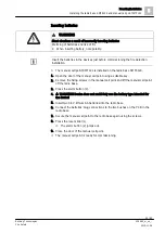
WARNING
Short-circuit as a result of incorrectly inserting batteries
Warming of batteries and risk of fire
●
When inserting battery, note polarity.
w
The detector line is switched off.
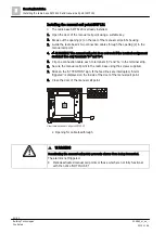
1. Remove the two stickers featuring the serial number from the back box.
2.
NOTICE! Do not stick any stickers on the radio module! The stickers may
impair the send and receive properties of the radio module.
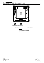
3. Stick one sticker in the battery compartment of the radio gateway so that you
can identify the radio gateway even when it is screwed down.
The other sticker is intended for sticking in the building plan.
4. Break out the cable entries according to the cable supply.
Recess-mounted cable entry:
Break out openings in supporting surface of back box.
Surface-mounted cable entry:
Break open openings in face end of back box.
5. Guide cables through back box and use two screws (max. diameter 4.3 mm) to
fit back box on a level surface.
6. Prepare the detector line wires such that they can be connected to the 'LINE'
spring clip later on.
7. Connect negative and positive poles of the detector line with a micro terminal
or connection terminal (order separately). To test the detector line, these must
not be interrupted.
8. If the detector line cables are shielded, connect the shieldings of the two
detector line cables (coming and going) to the 'SHIELD' spring clips. Use a
screwdriver to remove the load from the spring clip so you can slide in the wire.
9. Connect clip to 9 V battery contacts and insert battery in back box's battery
compartment. Only connect battery cable to connector on PCB when
commissioning.
10. Snap housing cover onto back box.
The shielding must not touch any other potentials or metal parts in the device.
See also
2

