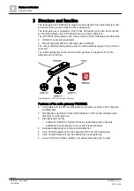
Structure and function
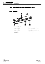
Structure of the radio gateway FDCW221
3
22 | 82
Building Technologies
009865_m_en_--
Fire Safety
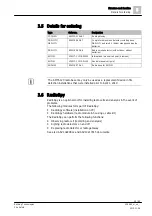
2015-11-06
3.1.3 Connections
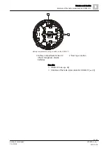
The radio gateway FDCW221 has connections for:
●
The FDnet detector line
●
The shieldings of the detector line cables
The two 'SHIELD' connection terminals are internally linked to one another.
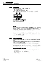
Connections on FDCW221 radio gateway
1 Shield connection terminal blocks
for detector lines
2 Spring clips for the FDnet detector
line
MC link
The MC link connection in the radio gateway is mainly used to connect the detector
exchanger and tester FDUD292 and the intelligent detector tester FDUD293 (as of
software V2.1). These devices allow information to be read from the radio gateway
for commissioning, maintenance and troubleshooting.
You will find more information in documents 007227 and 009718.
The MC link is also used to update the radio gateway firmware. The MCL-USB
adapter FDUZ221 is used to lead the firmware from the PC to the radio gateway.
You will find a description of firmware update in chapter 'Updating the firmware of
For details, see document 009854.
3.1.4 Radio transmission
The radio module SPU60xx consists of a printed circuit board with two integrated
aerials.
The radio module is a module which allows for bidirectional data transmission in
the 868...870 MHz frequency range.
The radio module has a complete send and receive unit and a microcontroller
control unit for all radio transmission functions.
Radio transmission takes place in the SRD band (Short Range Device), a reserved
frequency band with defined usage rules. The SRD band is free from amateur
users. The SRD band provides 80 channels with a channel width of 25 kHz.
Characteristics of the SRD band:
●
Defined low maximum transmitting powers and duty cycle (ratio between
send/idle time)
●
Sub-bands for various uses and applications
●
High availability
LINE
+
+
_
_
+
_
SHIELD
2
1


