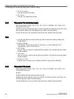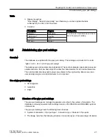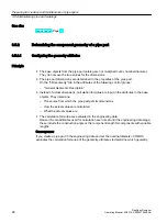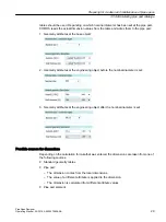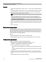
4. Ensure that the calculation formulas are entered correctly and completely in the fields for
the specification of the bolt set. See also chapter Determining the component geometry of
Alternatively, you can enter the values manually without having them calculated.
5. Drag&drop a prepared bolt set into the "Bolt set" field.
6. To define two bolted types at the connector of the pipe part, proceed as described above
in the control group "Information - Second bolt circle".
Result
The defined bolt sets are generated and connected to the associated pipe parts during the bolt
calculation.
3.5.4
Nominal diameter range of a pipe part
3.5.4.1
Introduction to nominal diameter ranges
The base objects of the pipe parts from the pipe part catalog are almost completely specified
templates that are parameterized according to nominal diameter. This means that a
manufacturer device can be assigned by setting the nominal diameter.
A nominal diameter can only be assigned to a manufacturer device if it lies in the nominal
diameter range of the pipe part.
COMOS validates the permitted nominal diameter ranges of a pipe part and saves them at the
corresponding object. Regarding the nominal diameter, a pipe part counts as permitted if the
following requirements are met:
● All 3D attributes of the "3D geometry" tab entered via the user interface have to be
calculable.
● The values that are relevant for calculating the geometry have to be calculable.
The calculated nominal diameter range is saved at the pipe part as an XML string in the
"Y00A04288 Nominal diameter range" attribute on the "3D geometry" tab.
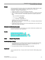
The nominal diameter range of a pipe part can also be displayed on the user interface. See
also chapter Display nominal diameter range (Page 40).
For pipe-spec-dependent pipe parts for which the function "CatPC" has been set, the XML
string is created underneath the pipe spec element.
3.5.4.2
Display nominal diameter range
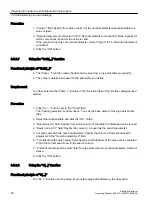
The pipe parts in the pipe part catalog are configured in such as way as standard that you can
read the nominal diameter range in the characteristics on the "Display for nominal diameter
range" tab.
If you create a new pipe part type in the template of the pipe part catalog under the node "@30
> M23 > A50 > A10 > A10 > A10 Pipe part catalog template", you must link the "Y00T00057
Display for nominal diameter range" tab.
Preparing for creation and maintenance of pipe specs
3.5 Administering pipe part catalogs
PipeSpec Designer
40
Operating Manual, 09/2014, A5E32076948-AA
Содержание COMOS
Страница 8: ...Table of contents PipeSpec Designer 8 Operating Manual 09 2014 A5E32076948 AA ...
Страница 10: ...Publisher PipeSpec Designer 10 Operating Manual 09 2014 A5E32076948 AA ...
Страница 70: ...Calling the PipeSpec Designer PipeSpec Designer 70 Operating Manual 09 2014 A5E32076948 AA ...
Страница 118: ...Documenting pipe specs PipeSpec Designer 118 Operating Manual 09 2014 A5E32076948 AA ...
Страница 120: ...Creating a revision of pipe specs PipeSpec Designer 120 Operating Manual 09 2014 A5E32076948 AA ...

