Semiconductor Group
7-19
1997-10-01
Interrupt System
C541U
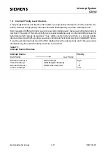
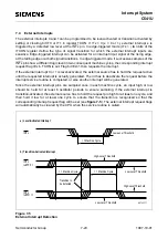
Note that if an interrupt of a higher priority level goes active prior to S5P2 in the machine cycle
labeled C3 in figure 7-4 then, in accordance with the above rules, it will be vectored to during C5
and C6 without any instruction for the lower priority routine to be executed.
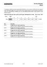
Thus, the processor acknowledges an interrupt request by executing a hardware-generated LCALL
to the appropriate servicing routine. In some cases it also clears the flag that generated the
interrupt, while in other cases it does not; then this has to be done by the user’s software. The
hardware clears the external interrupt flags IE0 and IE1 only if they were transition-activated. The
hardware-generated LCALL pushes the contents of the program counter onto the stack (but it does
not save the PSW) and reloads the program counter with an address that depends on the source of
the interrupt being vectored too, as shown in the following table 7-2.
Execution proceeds from that location until the RETI instruction is encountered. The RETI
instruction informs the processor that the interrupt routine is no longer in progress, then pops the
two top bytes from the stack and reloads the program counter. Execution of the interrupted program
continues from the point where it was stopped. Note that the RETI instruction is very important
because it informs the processor that the program left the current interrupt priority level. A simple
RET instruction would also have returned execution to the interrupted program, but it would have
left the interrupt control system thinking an interrupt was still in progress. In this case no interrupt of
the same or lower priority level would be acknowledged.
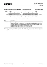
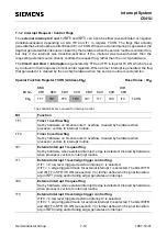
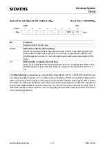
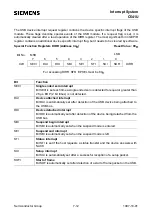
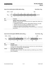
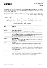
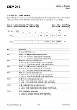
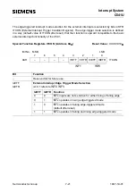
A special interrupt source is the power-down mode interrupt. This interrupt is automatically enabled
when the C541U is in power-down mode and bit EWPD (enable wake-up from power-down mode)
in SFR PCON1 is set. If these two conditions are met and when the oscillator watchdog unit start-
up phase after a wake-up condition (INT0=0) is finished, the C541U starts with an interrupt at
address 007BH. All other interrupts are now disabled until the RETI instruction of the power-down
interrupt routine has been executed.
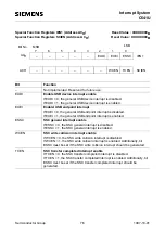
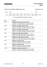
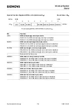
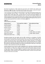
Table 7-2
Interrupt Source and Vectors
Interrupt Source
Interrupt Vector Address
Interrupt Request Flags
External Interrupt 0
0003H
IE0
Timer 0 Overflow
000BH
TF0
External Interrupt 1
0013H
IE1
Timer 1 Overflow
001BH
TF1
SSC Interrupt
0043H
TC, WCOL
USB Endpoint Interrupt
004BH
in SFRs EPIR0-4 and GEPIR
USB Device Interrupt
0053H
in SFRs DIRR and GEPIR
Wake-up from power down
007BH
–
Содержание C541U
Страница 1: ... 8 LW 026 0LFURFRQWUROOHU 8VHU V 0DQXDO http www siem ens d Sem iconductor ...
Страница 7: ......
Страница 21: ...Semiconductor Group 2 6 1997 10 01 Fundamental Structure C541U ...
Страница 37: ...Semiconductor Group 4 6 1997 10 01 External Bus Interface C541U ...
Страница 133: ...Semiconductor Group 6 88 1999 04 01 On Chip Peripheral Components C541U ...
Страница 163: ...Semiconductor Group 8 8 1997 10 01 Fail Safe Mechanisms C541U ...
Страница 185: ...Semiconductor Group 10 14 1997 10 01 OTP Memory Operation C541U ...
Страница 192: ...Semiconductor Group 12 7 Index C541U ...

